Connecting device, and connector comprising such a device

a technology of connecting device and connector, which is applied in the direction of pipe/joint/fitting, coupling, pipe-joint, etc., can solve the problems of high cam lever force, compactness and/or strength, and achieve significant compactness and reduce contact pressure

Active Publication Date: 2017-02-07
STAUBLI FAVERGES SA
View PDF9 Cites 0 Cited by
  • Summary
  • Abstract
  • Description
  • Claims
  • Application Information

AI Technical Summary

Benefits of technology

[0016]a third articulation diameter between the connecting rod ring member and the rear housing around a third axis;in that the first, second and third axes are separate and parallel to a direction transverse to the longitudinal axis;in that the distance between the first axis and the second axis is smaller than the half-sum of the first diameter and the second diameter;in that the distance between the second axis and the third axis is smaller than the half-sum of the second diameter and the third diameter; andin that the pivot member is movable only in translation along the longitudinal axis relative to the end body and is capable of pushing the pipe end back in the direction.
[0017]Thus, the connecting device according to the invention has many advantages, which will emerge from the description below. In particular, the connecting device makes it possible to obtain a reliable and ergonomic connection between two connector elements, by implementing displacement means procuring reduced contact pressures and significant compactness.

Problems solved by technology

In practice, this sealing requires exerting high forces on the cam lever on the contact surfaces.
The contacts between the cam supported by the lever and the ring to be moved are linear contacts, which poses a problem of compactness and / or strength when the materials, in particular for reasons of compatibility with certain fluids, do not have a sufficient hardness to withstand caulking.

Method used


Image

  • Connecting device, and connector comprising such a device
  • Connecting device, and connector comprising such a device
  • Connecting device, and connector comprising such a device

Examples


Embodiment Construction

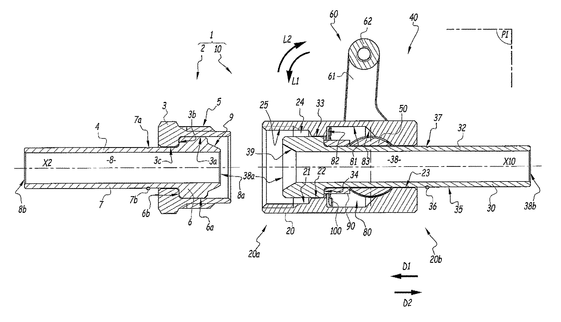
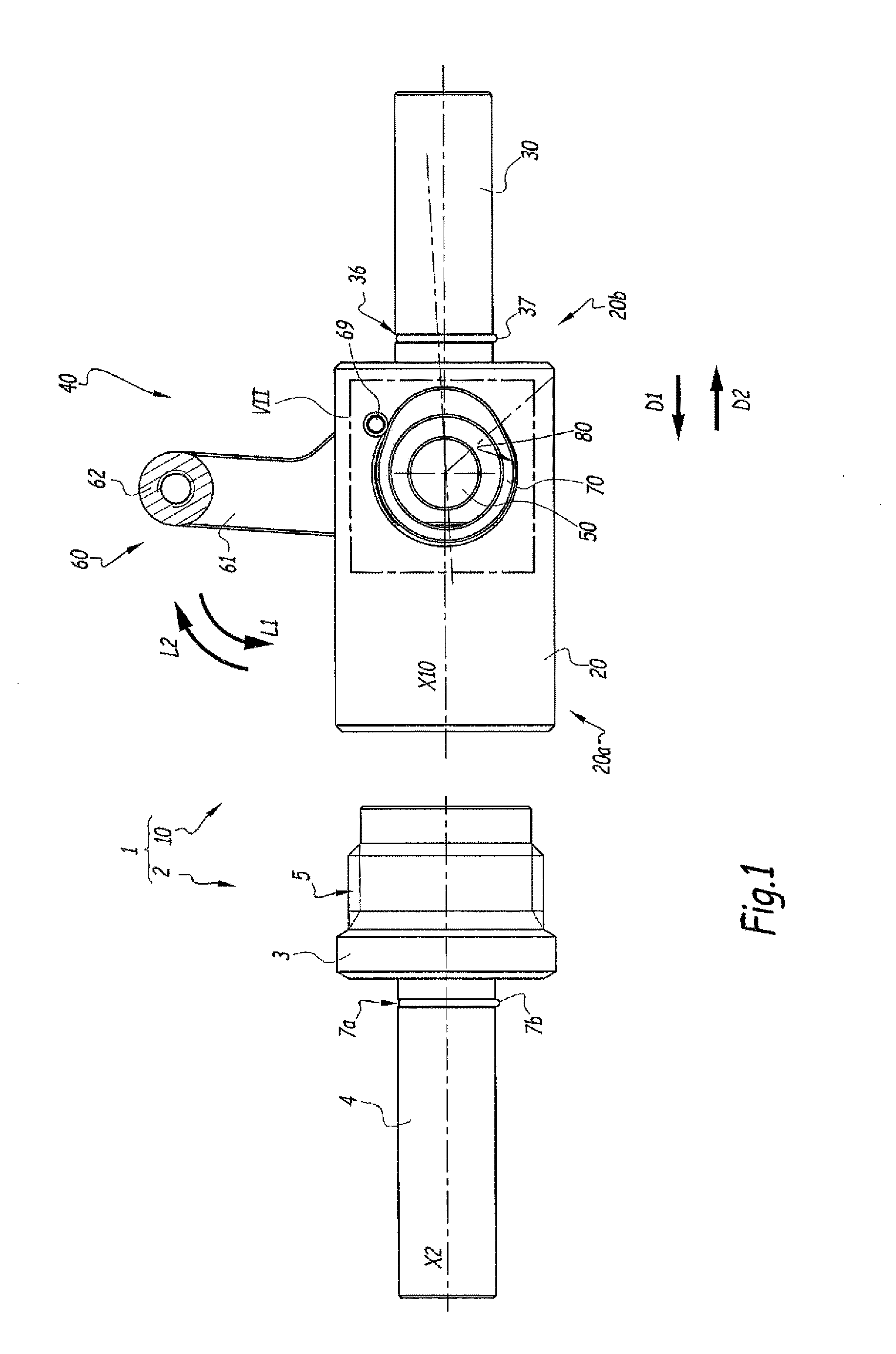
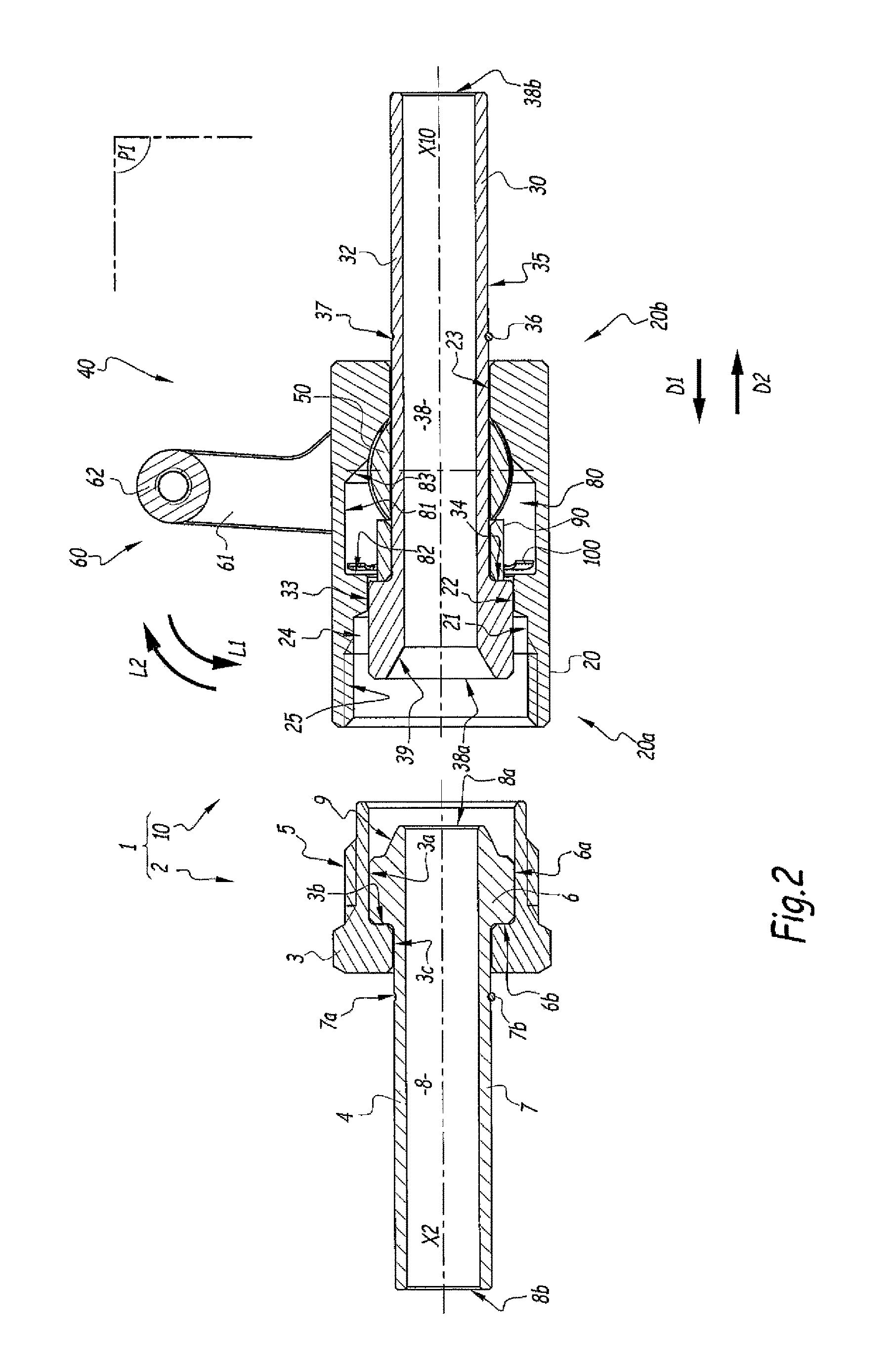
[0042]FIGS. 1 to 8 show a connector 1 according to the invention.

[0043]This connector 1 comprises a connector element 2 and a connecting device 10, which is also according to the invention. The element 2 is configured as a male connector end, while the device 10 is configured as a female connector end, adapted for receiving the element 2. The device 10 is provided to be connected to a first line, while the element 2 is provided to be coupled to the connecting device 10 and to be connected to a second line, these lines not being shown in FIGS. 1 to 8 for simplification purposes. The connector 1 is shown in a separated configuration in FIGS. 1, 2 and 7, during coupling in FIG. 3, and in a coupled configuration in FIGS. 4, 5 and 8.

[0044]The element 2 and the device 10 are the two component elements of the connector 1 adapted for transmitting gaseous and / or liquid fluids under high pressures and high temperatures (up to 450° C.) or very low temperatures (for example up to −250° C.) when...


PUM


Abstract

A connecting device for transmitting pressurized fluids including a pipe having an inner flow channel, a body including an inner cavity isolated from the inner flow channel, and a displacement member for moving the pipe in the body between an unlocked configuration and a locked configuration and wherein the displacement member includes a pusher member movable within the body, an off-centered member connected to the slide member, a connecting rod ring and a rear housing formed in the body, defining a first articulation diameter (φ1) between the pusher member and the off-centered member around a first axis (A1), a second articulation diameter (φ2) between the off-centered member and the connecting rod member around a second axis (A2), and a third articulation diameter (φ3) between the connecting rod ring and the rear housing around a third axis (A3) and wherein the three axes are separate and parallel to a transverse direction transverse of the device.

Description

BACKGROUND OF THE INVENTION[0001]Field of the Invention[0002]The present invention relates to a connecting device. The invention also relates to a connector comprising such a device.[0003]The field of the invention is that of connectors adapted for the passage of fluids under high pressures and high or very low temperatures, which require maximum safety and demand sealing using metal parts. Advantageously, such sealing is achieved by metal-on-metal contact without using a seal made from a polymer material. The invention is well suited to specific applications in the field of cryogenics.[0004]Brief Description of the Related Art[0005]GB-A-163,053 describes a connecting device between two tubes. A first tube is screwed into a main coupling element provided with a first frustoconical surface. The second tube is screwed into a coupling ring provided with a second frustoconical surface and mounted sliding in the main element. The device also comprises a cam lever, mounted on the coupling...

Claims


Application Information

Patent Timeline
Patent Type & Authority Patents(United States)
IPC IPC(8): F16L37/18F16L19/02
CPCF16L37/18F16L19/0225
Inventor TIBERGHIEN, ALAIN-CHRISTOPHEDURIEUX, CHRISTOPHEBAHNO, IGOR
Owner STAUBLI FAVERGES SA
Why Eureka
Try Eureka