
Bed positioning system for radiation therapy

a positioning system and radiation therapy technology, applied in the direction of patient positioning for diagnostics, therapy, application, etc., can solve the problems of deteriorating the throughput of treatment, long time, and error

Active Publication Date: 2017-02-14
HITACHI LTD
View PDF5 Cites 2 Cited by
  • Summary
  • Abstract
  • Description
  • Claims
  • Application Information

AI Technical Summary

Benefits of technology

The present invention aims to achieve high-accuracy bed positioning by removing a structure, such as a bow-tie filter, from images used for the positioning calculation. This is done without the need for previously preparing many pieces of correction image data. The technical effect of the invention is to improve the accuracy of bed positioning in a more efficient and straightforward manner.

Problems solved by technology

On the other hand, an error can occur if an X-ray image in which the bow-tie filter has been captured is directly used for the 3D / 2D registration.
However, the detachment of the bow-tie filter takes a long time and that deteriorates the throughput of the treatment.
As described above, it is difficult to remove the bow-tie filter from the image by using the structure information alone.
In reality, the removal process has to be carried out by using information on a plurality of bow-tie filter projection images captured in various X-ray image capturing conditions as the structure information and it is difficult to employ such a method for the actual radiation therapy.

Method used


Image

  • Bed positioning system for radiation therapy
  • Bed positioning system for radiation therapy
  • Bed positioning system for radiation therapy

Examples


first embodiment

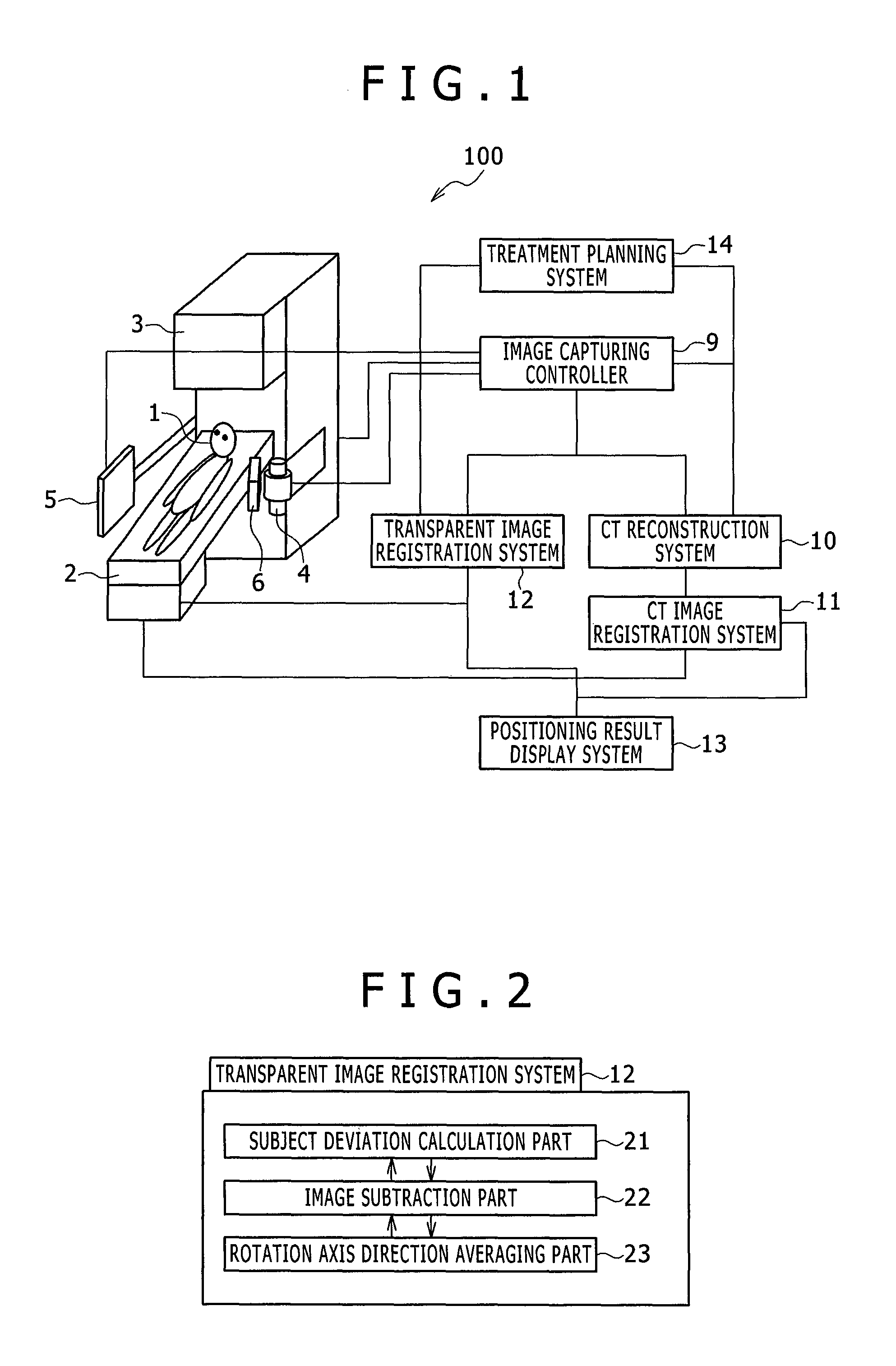
[0024]A first embodiment of the present invention will be described below by taking a bed positioning system performing the 3D / 2D registration as an example. FIG. 1 is a schematic block diagram showing an example of the configuration of a bed positioning system 100 in accordance with the first embodiment of the present invention. A subject 1 to receive the radiation therapy is supported on a bed (support table) 2. The bed 2 is equipped with a drive mechanism for parallel translation and rotation, and thus the bed 2 supporting the subject 1 can be moved by the drive mechanism. A therapeutic radiation irradiation system 3, having a rotation mechanism, is capable of applying the therapeutic radiation to the subject 1 from any direction (angle) around the rotation axis.

[0025]The therapeutic radiation irradiation system 3 is equipped with an X-ray tube 4 and an X-ray detector 5 via support arms. According to the rotation of the therapeutic radiation irradiation system 3, the X-ray tube 4...

second embodiment

[0043]A second embodiment of the present invention will be described below. In this embodiment, the rotation axis direction averaging part 23 in the transparent image registration system 12 for executing the 3D / 2D registration in the bed positioning system 100 described in the first embodiment is replaced with a rotation axis direction mode extraction part 24 shown in FIG. 5.

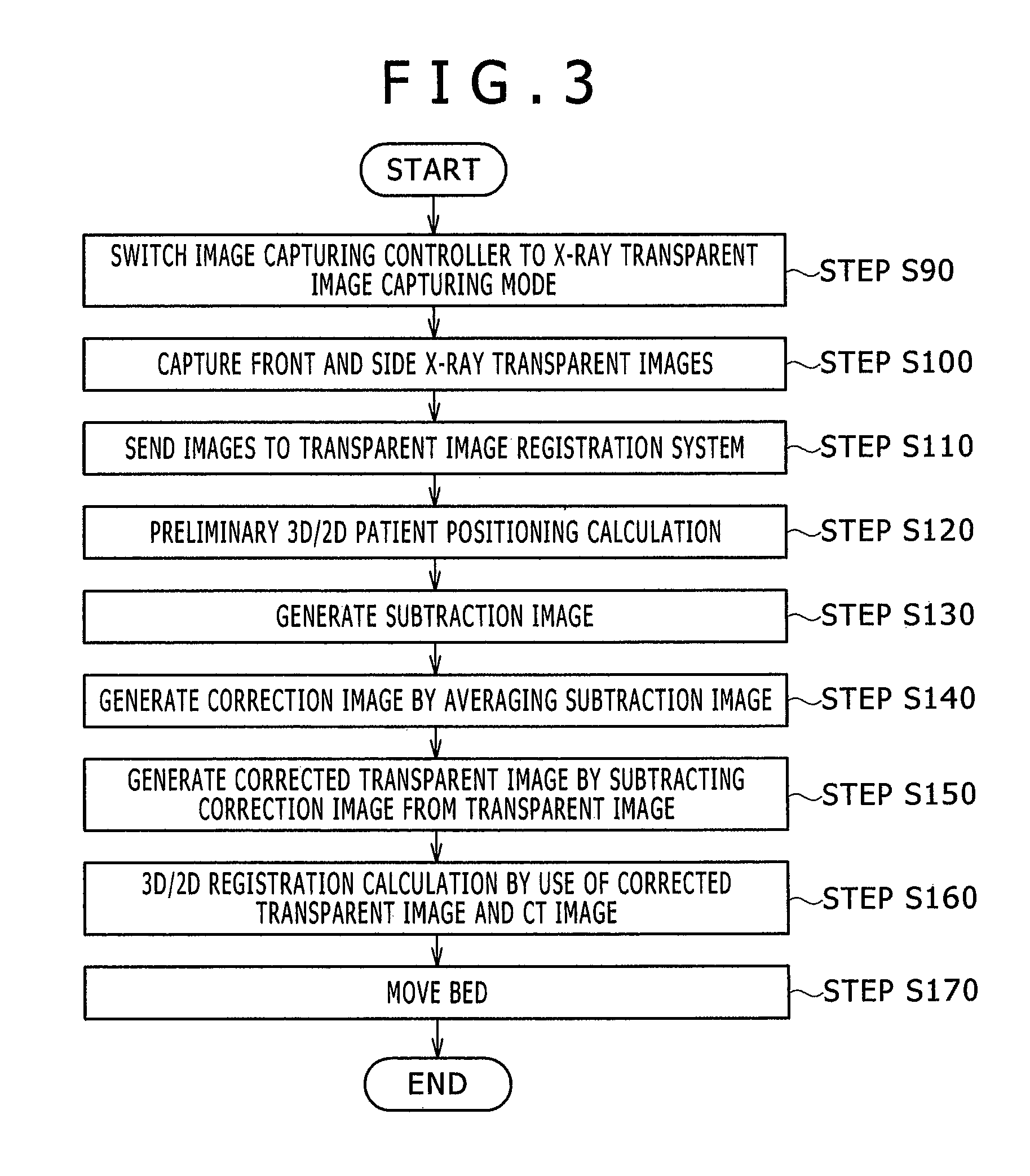
[0044]FIG. 6 is a flow chart showing the flow of a process executed in this embodiment. In FIG. 6, the step S140 in the flow chart of FIG. 3 is replaced with step S340. The process up to the generation of the subtraction images 220 is executed in the same flow as in the flow chart of the first embodiment (FIG. 3). In the step S340, the mode is determined instead of taking the average in the CT image rotation axis direction. The “mode” is determined as follows: Pixels in the image on a line in the CT image capturing axis direction are divided (classified) into pixel groups each having the same pixel value. The “m...


PUM


Abstract

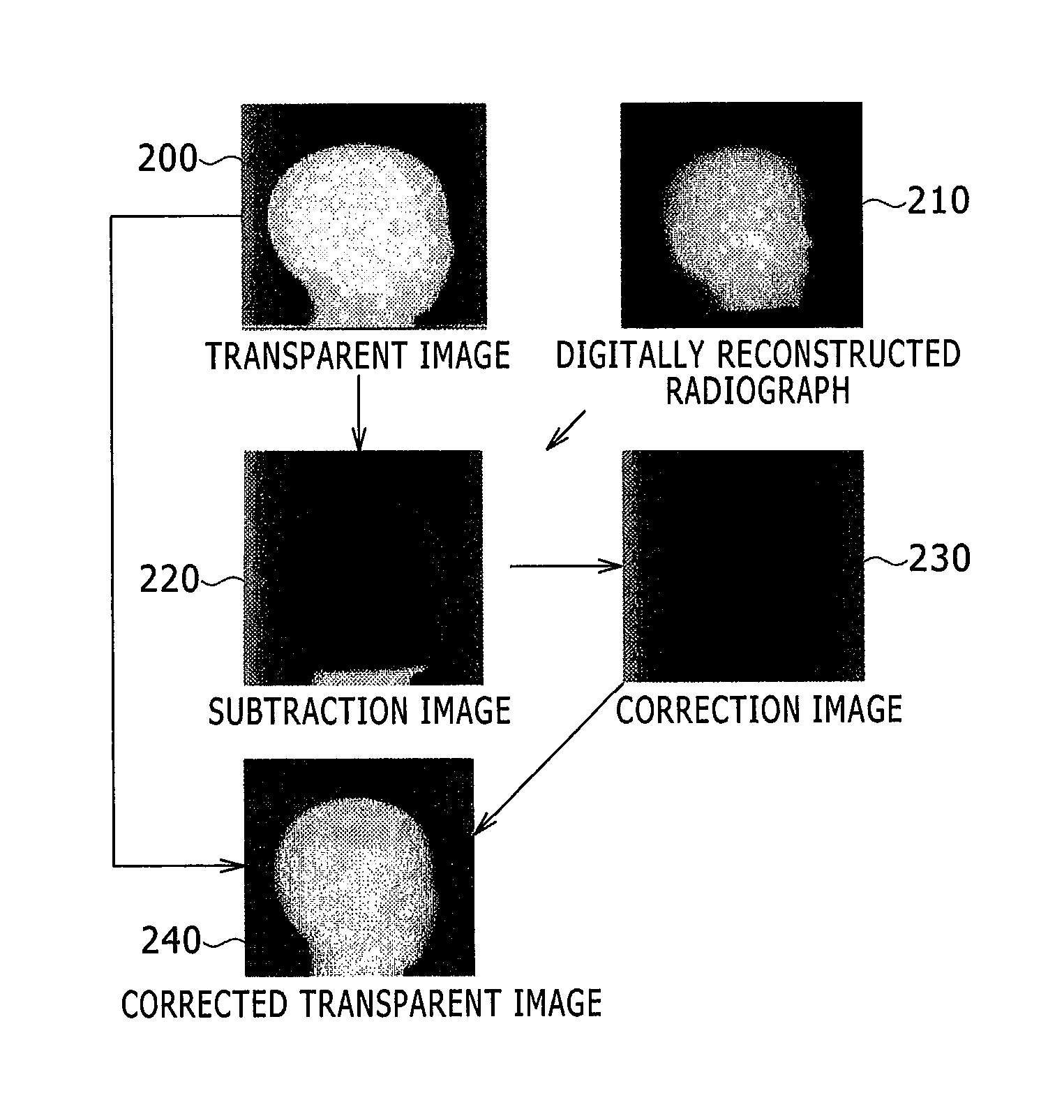
Provided is a bed positioning system for a radiation therapy system capable of capturing X-ray transparent images and CT images by rotating an X-ray tube and an X-ray detector around a subject on a bed, comprising: a transparent image registration system which generates a subtraction image from a first X-ray transparent image captured by the X-ray tube and the X-ray detector and a digitally reconstructed radiograph generated from a treatment plan CT image, corrects the first X-ray transparent image by use of a correction image generated by processing the subtraction image in a previously specified direction, and compares the first X-ray transparent image after the correction and the digitally reconstructed radiograph to determine a movement amount of the bed.

Description

BACKGROUND OF THE INVENTION[0001]1. Field of the Invention[0002]The present invention relates to a bed positioning system for radiation therapy.[0003]2. Description of the Related Art[0004]During radiation therapy, X-ray transparent images of the subject (patient) on a bed are captured and the bed is positioned according to the result of comparison between the captured images and a reference image in the treatment plan so that the position of the subject coincides with a planned position (position specified in the treatment plan).[0005]In high-precision radiation therapy such as particle beam therapy and X-ray IMRT (Intensity Modulated Radiation Therapy), dose distribution concentrating at the target can be realized. Therefore, the positioning process is also required to position the target in the subject at the planned position with high accuracy.[0006]For the positioning at the time of treatment (radiation therapy), an X-ray transparent image or an X-ray CT (Computed Tomography) i...

Claims


Application Information

Patent Timeline
Patent Type & Authority Patents(United States)
IPC IPC(8): A61B6/03A61B6/00A61B6/04A61N5/10
CPCA61B6/5264A61B6/035A61B6/0407A61B6/0457A61B6/4035A61B6/5217A61B6/5247A61B6/5258A61N5/107A61N5/1049A61B6/032A61B6/486A61N2005/1061A61N2005/1062A61B6/0487
Inventor UMEKAWA, TORUAOKI, TAKAMICHI
Owner HITACHI LTD
Learn More