
Arrangement and method for capacitive sensing of the rotary movement of a rotary element

Inactive Publication Date: 2017-02-14
TECHEM ENERGY SERVICES
View PDF12 Cites 0 Cited by
  • Summary
  • Abstract
  • Description
  • Claims
  • Application Information

AI Technical Summary

Benefits of technology

The present invention aims to provide a better way to sense the motion of a rotary member. The invention reduces the complexity of evaluating the motion and allows for a smaller installation space for the overall electrode configuration.

Problems solved by technology

The detection of the voltage signals of these four electrodes requires a higher degree of complexity of the electronics and a comparably large installation space for the electrodes and the connection lines leading to the evaluation electronics.
But precisely this installation space is often not available when using the configuration according to the invention in a supply meter, because the installation space in supply meters is limited.

Method used


Image

  • Arrangement and method for capacitive sensing of the rotary movement of a rotary element
  • Arrangement and method for capacitive sensing of the rotary movement of a rotary element
  • Arrangement and method for capacitive sensing of the rotary movement of a rotary element

Examples


Embodiment Construction

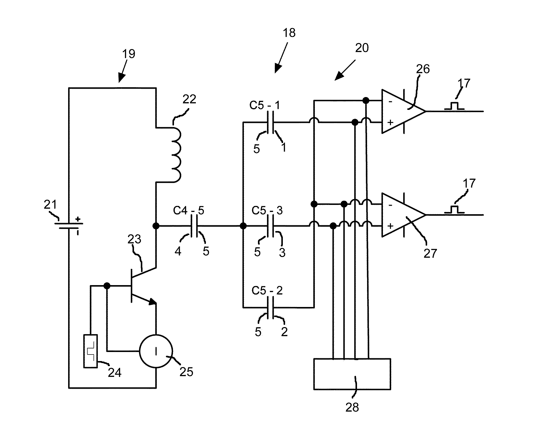
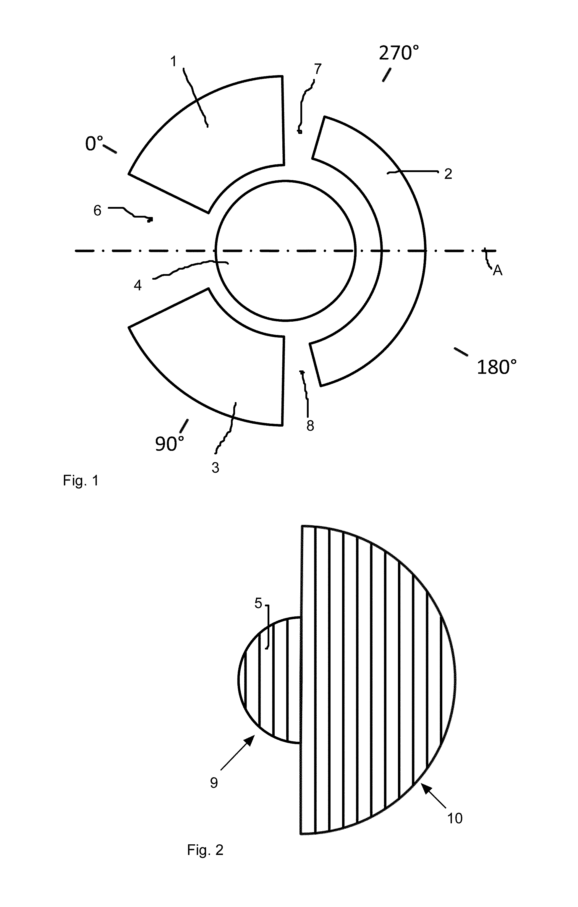
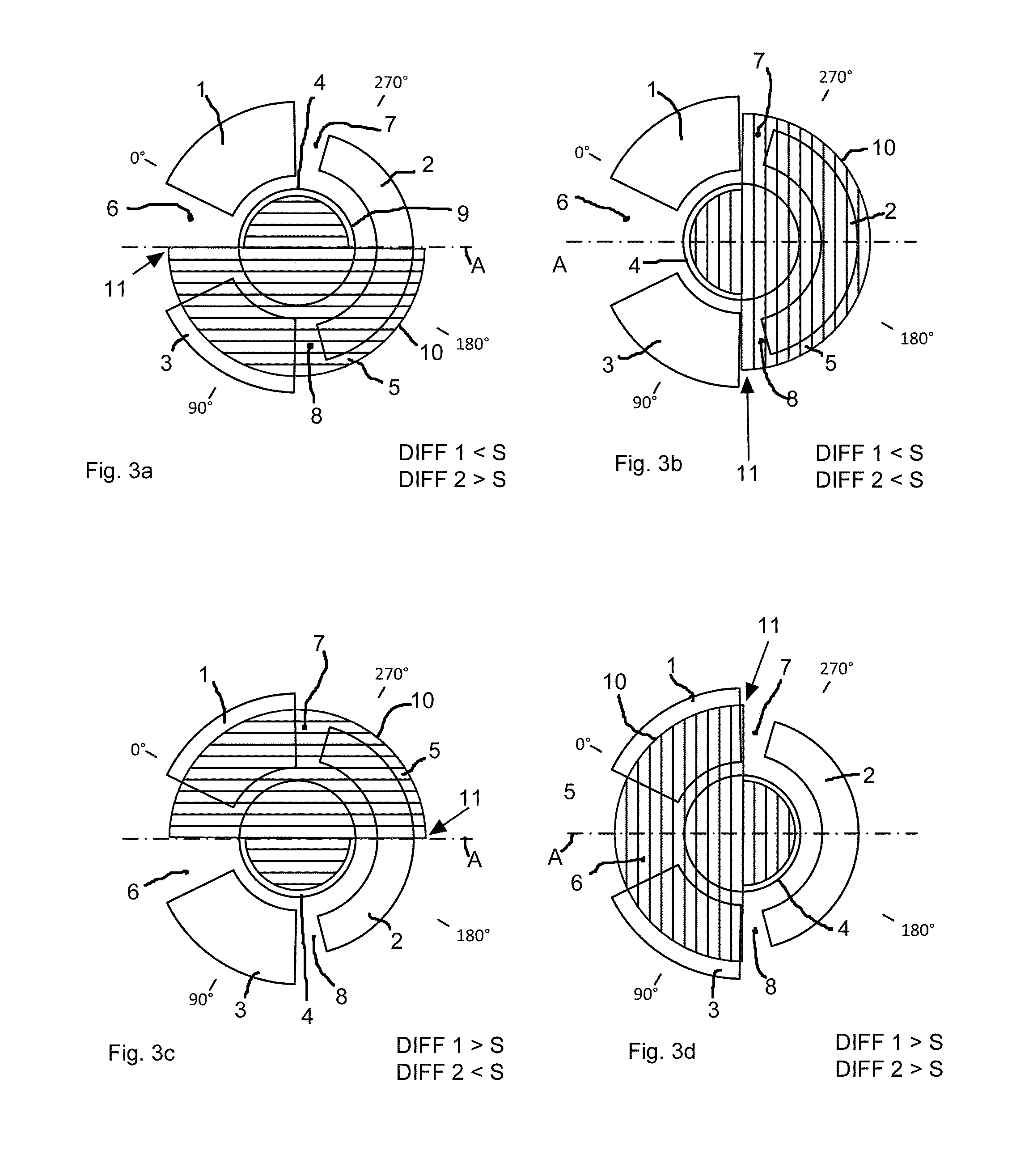
[0054]FIG. 1 schematically shows the arrangement of the electrodes in the configuration according to the invention for capacitative sensing of the rotatory motion of a rotary member. This configuration consists of a first sensor electrode 1, a reference electrode 2, a second sensor electrode 3 and an excitation electrode 4. Opposite to this electrode configuration shown in FIG. 1, a coupling surface 5 consisting of an electrically conducting material is located that is shown in FIG. 2, which is displaced over the electrode arrangement according to FIG. 1 upon a rotatory motion of the rotary member.

[0055]In a particularly preferred configuration to which the present invention is, however, not limited, excitation electrode 4 is structured circular, around which the remaining electrodes, i.e. the first and the second sensor electrode 1, 3 and the reference electrode 2 are located. The first and the second sensor electrode 1, 3 are designed identical and have the shape of a segment of a...


PUM


Abstract

A configuration and a method for capacitive sensing of the rotatory motion of a rotary member are described. The configuration has four electrodes located in one plane, an analysis unit connected to the electrodes and an electrically conducting coupling surface, which is located at the rotary member opposite to the electrodes. The electrodes comprise a central excitation electrode, surrounded by the other electrodes. The coupling surface is opposite to the surface of the excitation electrode in each rotary position and covers a part of the surface formed by the remaining electrodes and passes over the surface formed by the remaining electrodes during a rotation of the rotary member. The remaining electrodes are formed by two sensor electrodes and a joint reference electrode, whereby at least the joint reference electrode is designed different than the sensor electrodes.

Description

CROSS REFERENCE TO RELATED APPLICATIONS[0001]The present application is a 35 U.S.C. 371 National Application of PCT / EP2012 / 050504 filed Jan. 13, 2012, which claims priority to German Patent Application No. 10 2011 015 589.9, filed Mar. 30, 2011, the entire contents of which are incorporated entirely herein by reference.BACKGROUND[0002]The invention relates to a configuration and a method for capacitative sensing of the rotatory motion of a rotary member, whereby the configuration has four electrodes located in one plane, an analysis unit connected to the electrodes and an electrically conducting coupling surface. The coupling surface is mounted at the rotary member, opposite to the electrodes, and is used for the capacitive coupling of the electrodes.[0003]The electrodes include a central excitation electrode which is surrounded by the other electrodes, whereby in every position of rotation, the coupling surface is opposite to the surface of the excitation electrode and substantiall...

Claims


Application Information

Patent Timeline
IPC IPC(8): G01R27/26G01P3/483G01D5/241
CPCG01R27/2605G01D5/2412G01P3/483
Inventor REUS, JURGEN
Owner TECHEM ENERGY SERVICES
Learn More