Apparatus and method for inline monitoring of transmission signals

a transmission signal and inline monitoring technology, applied in the direction of electrical equipment, radio transmission, electromagnetic transmission, etc., can solve the problem that the summary is not intended to be used, and achieve the effect of facilitating identification

Active Publication Date: 2017-02-14
HUGHES NETWORK SYST
View PDF1 Cites 0 Cited by
  • Summary
  • Abstract
  • Description
  • Claims
  • Application Information

AI Technical Summary

Benefits of technology

[0004]According to another embodiment, an apparatus includes a processor, one or more fiber optic lines for supplying a transmit signal to / from a remote transmission station, and a data acquisition unit for acquiring information from the one or more fiber optic lines. The processor is configured to receive input for selecting one or more fiber optic lines for examination, determine at least one property of the transmit signal to be monitored, and retrieve information corresponding to the at least one property for a predetermined period of time. The processor is further configured to output a visual representation of the retrieved information, perform an analysis of the retrieved information and the visual representation, and facilitate identification of at least one status associated with the transmit signal based, at least in part, on the analysis.

Problems solved by technology

Furthermore, this summary is not intended to be used as an aid in determining the scope of the claimed subject matter.

Method used


Image

  • Apparatus and method for inline monitoring of transmission signals
  • Apparatus and method for inline monitoring of transmission signals
  • Apparatus and method for inline monitoring of transmission signals

Examples


Embodiment Construction

[0027]An apparatus and method for inline monitoring of transmit signals, are described. In the following description, for purposes of explanation, numerous specific details are set forth in order to provide a thorough understanding of the disclosed embodiments. It will become apparent, however, to one skilled in the art that various embodiments may be practiced without these specific details or with an equivalent arrangement. In other instances, well-known structures and devices are shown in block diagram form in order to avoid unnecessarily obscuring the various embodiments.

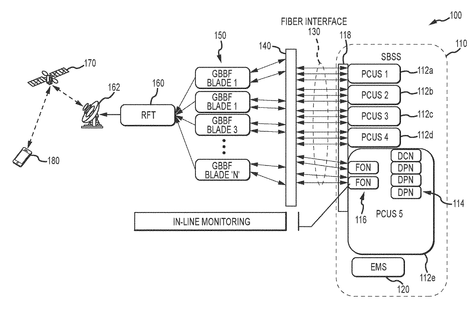
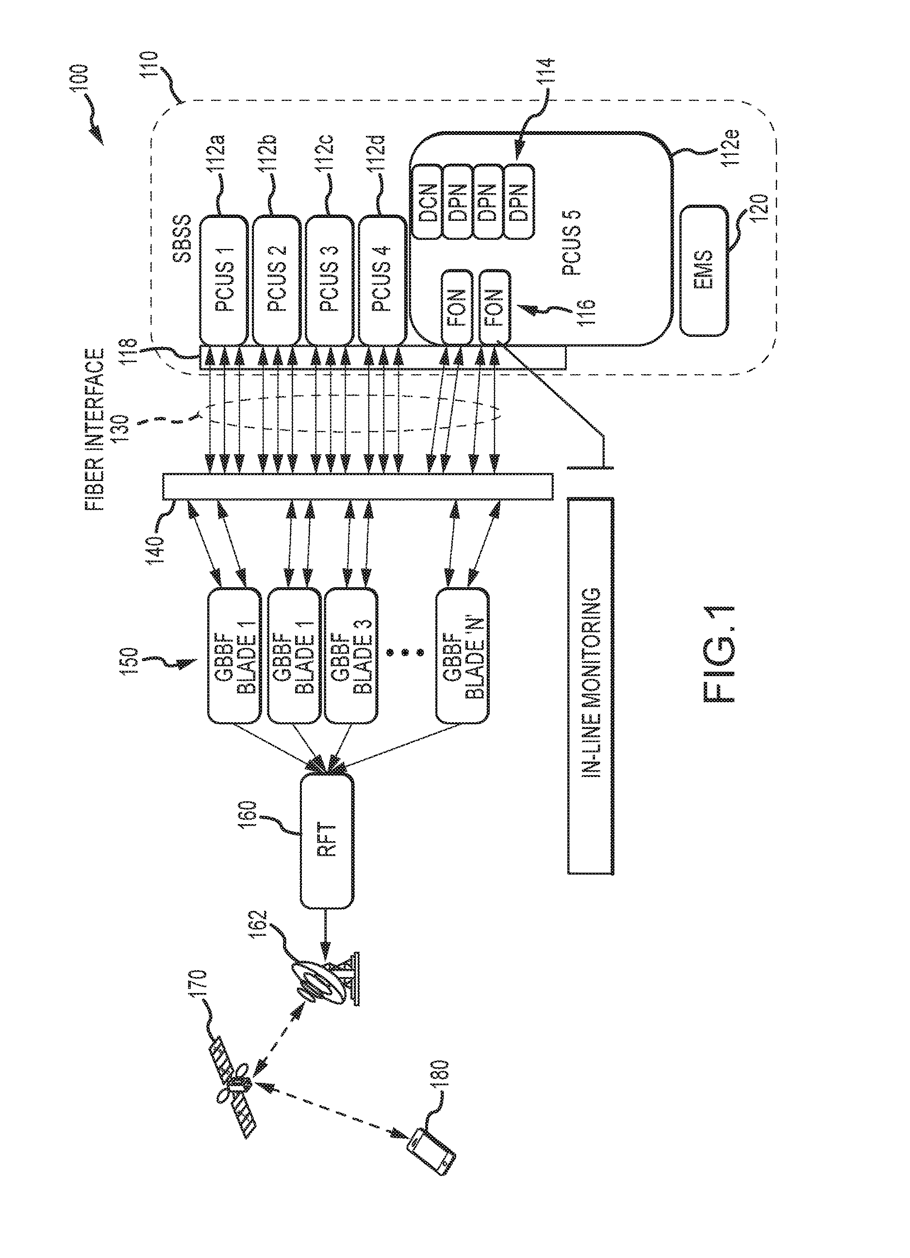
[0028]FIG. 1 is a diagram illustrating a system for inline monitoring of a transmission signal (or transmit signal), in accordance with at least one embodiment. As used herein, the term transmit (or transmission) signal corresponds to any signal (analog and / or digital) containing information such as data, control signals, etc. The data can include, for example, audio, video, speech, image, etc. The transmit sign...


PUM


Abstract

An apparatus for inline monitoring of transmit signals is disclosed. The apparatus includes a processor, and one or more fiber optic lines for supplying a transmit signal to / from a remote transmission station. The processor is configured to receive input for selecting one or more fiber optic lines for examination, determine at least one property of the transmit signal to be monitored, and retrieve information corresponding to the at least one property for a predetermined period of time. The processor is further configured to output a visual representation of the retrieved information, perform an analysis of the retrieved information and the visual representation, and facilitate identification of at least one status associated with the transmit signal based, at least in part, on the analysis.

Description

BACKGROUND INFORMATION[0001]Modern communication systems are complex and require the use of a great number of hardware components for proper operation. Hardware components, however, can be subject to malfunction and failure. Such failure can result in significant system downtime and / or customer dissatisfaction. Depending on the particular hardware, for example, customers may be unable to access some or all features of the system including data, voice, etc. Furthermore, customers may contact service centers to voice dissatisfaction, possibly resulting in a desire to change service providers. It is also necessary to staff sufficient representatives to address customer concerns, thereby resulting in additional costs for the service provider.[0002]Identifying the cause of hardware malfunction can be difficult due to the overall complexity of the system. For example, an individual substation within a communication network can have a great number of hardware components that are susceptibl...

Claims


Application Information

Patent Timeline
Patent Type & Authority Patents(United States)
IPC IPC(8): H04B10/079
CPCH04B10/0795H04B10/0791H04B10/07955H04B7/185
Inventor DURVASULA, BHANU P.MUHAMMAD, TARIQTENDER, NEIL H.CHITALWALA, ESMAIL H.SAAD, ALEX
Owner HUGHES NETWORK SYST
Why Eureka
Try Eureka