Combination physiologic sensor

a physiologic sensor and comb technology, applied in the field of physiologic sensors, can solve the problems of inability to sleep comfortably for patients and inability to improve patient comfor

Active Publication Date: 2017-02-21
DYMEDIX
View PDF14 Cites 13 Cited by
  • Summary
  • Abstract
  • Description
  • Claims
  • Application Information

AI Technical Summary

Problems solved by technology

With all of these wires involved, it is often difficult for a patient to sleep comfortably, especially to be able to periodically roll over in bed.
This too is inimical to patient comfort.

Method used


Image

  • Combination physiologic sensor
  • Combination physiologic sensor
  • Combination physiologic sensor

Examples


Embodiment Construction

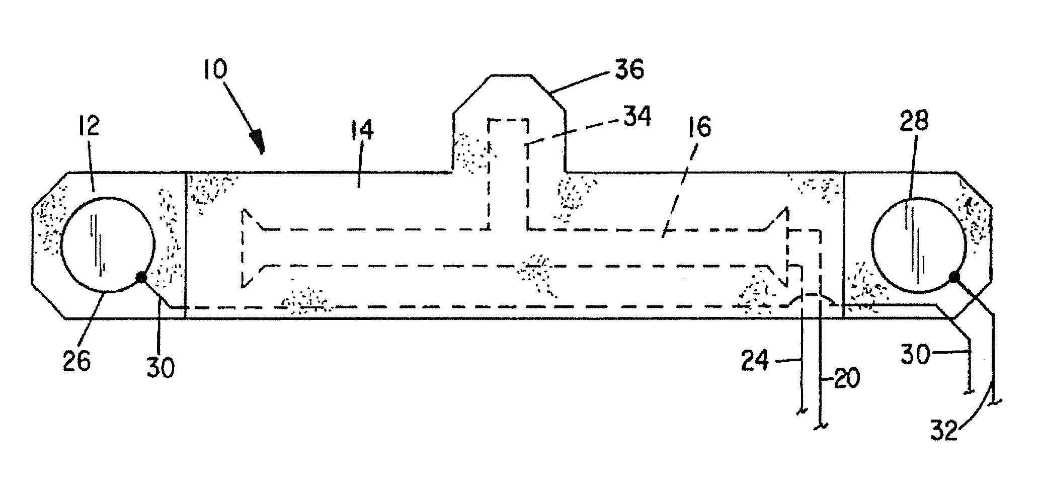
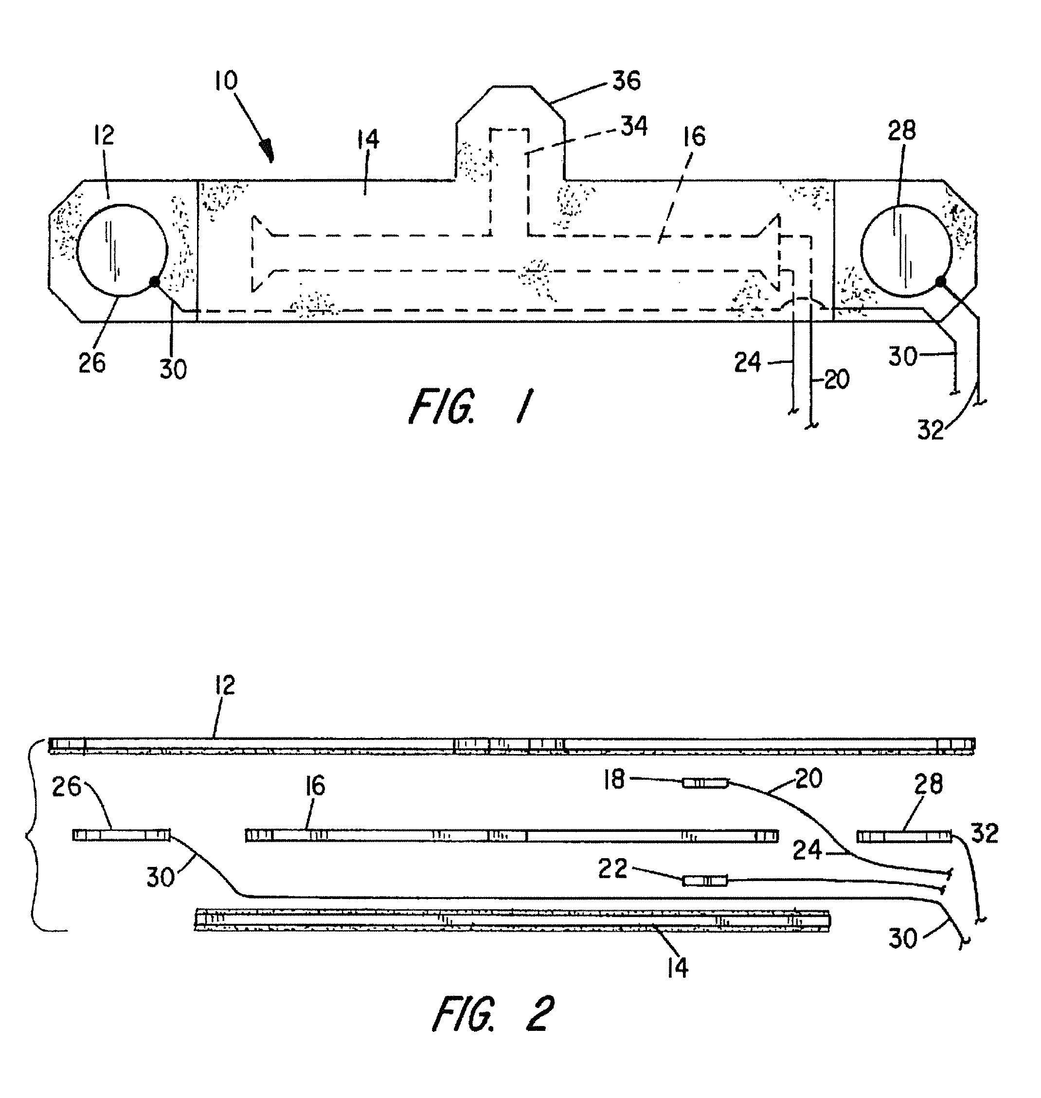
[0014]Referring to the drawings, the combination physiologic sensor is indicated generally by numeral 10 and is seen to comprise a strip 12 of a single-sided adhesive tape and a strip 14 of a double-sided adhesive tape and with a strip of a PVDF polymer 16 sandwiches there between. The polymer strip 16 has a thin layer of metallization on opposed major surfaces thereof and conductively attached to the metallization layer on the upper surface of the polymer strip 16 is a terminal pad 18 having an elongated insulated lead 20 conductively attached at its distal end to the pad 18. Likewise, a terminal pad 22 is conductively affixed to the metallization layer on the lower surface of the polymer strip 16 and an elongated lead 24 has its conductor wire attached at its distal end to the pad 22.

[0015]Affixed by the adhesive on the single-sided tape strip 12 are first and second conductive electrodes 26 and 28 each with an insulated electrical lead 30, 32 conductively attached thereto. It is ...


PUM


Abstract

A multi sensor module especially designed for use in sleep-study applications includes a PVDF film piezoelectric transducer enclosed between an upper layer of a single-sided adhesive tape strip and a lower layer of a double-sided adhesive tape strip. Also adhesively affixed to the upper single-sided adhesive tape strip, but not overlaid by the lower double-sided adhesive tape strip are first and second conductive electrodes. The combination sensor module is adapted to be adhesively affixed to the chest area of a person and further included in an extension of the PVDF strip that is adapted to overlay the suprasternal notch of a person for producing signals responsive to respiratory activity of the person.

Description

CROSS REFERENCE TO RELATED APPLICATIONS[0001]NoneRELATED GOVERNMENT RESEARCH[0002]NoneBACKGROUND OF THE INVENTION[0003]I. Field of the Invention[0004]This invention relates generally to physiologic sensors, and more particularly to a sensor module which when affixed to a person's chest will provide information related to respiratory effort, cardiac rhythm and sleep apnea.[0005]II. Discussion of the Prior Art[0006]In conducting a sleep study on a patient, it is customary to append a plurality of sensors to the patient for measuring and recording a number of physiologic parameters including, but not limited to, rapid eye movement, electric myograph (EMG), electrocardiograph (ECG), respiratory air flow, respiratory effort, cardiac rhythm, leg twitches, etc. Typically, individual sensors will be placed on the head, face, chest, abdomen and legs. The sensors typically have elongated electrical wire leads for connection to electronic display and recording modules. With all of these wires ...

Claims


Application Information

Patent Timeline
Patent Type & Authority Patents(United States)
IPC IPC(8): A61B5/0408A61B5/00A61B5/113A61B5/0205A61B5/08
CPCA61B5/04087A61B5/6823A61B5/0205A61B5/0809A61B5/1135A61B5/4818A61B2560/0412A61B2562/0209A61B2562/06A61B2562/164A61B5/259A61B5/257
Inventor MOORE, JAMES P.EIKEN, TODD M.
Owner DYMEDIX
Why Eureka
Try Eureka