Illumination system and luminaire

a technology of illumination system and luminaire, which is applied in the direction of lighting apparatus, electrical equipment, light sources, etc., can solve the problem of insufficient color toning range, and achieve the effect of reducing the color toning rang

Inactive Publication Date: 2017-02-28
PANASONIC INTELLECTUAL PROPERTY MANAGEMENT CO LTD
View PDF16 Cites 0 Cited by
  • Summary
  • Abstract
  • Description
  • Claims
  • Application Information

AI Technical Summary

Benefits of technology

[0007]In view of this, an object of the present disclosure is to provide an illumination system and a luminaire which allow broadening of the color toning range.
[0009]Illumination systems and luminaires according to the present disclosure allow broadening of the color toning range.

Problems solved by technology

However, the luminaire disclosed in PTL 1 has the problem that the color toning range is not sufficiently broad.

Method used


Image

  • Illumination system and luminaire
  • Illumination system and luminaire
  • Illumination system and luminaire

Examples


embodiment

[0042]An illumination system and a luminaire including the illumination system in an embodiment will be described using FIG. 3 to FIG. 6, and FIG. 7A and FIG. 7B.

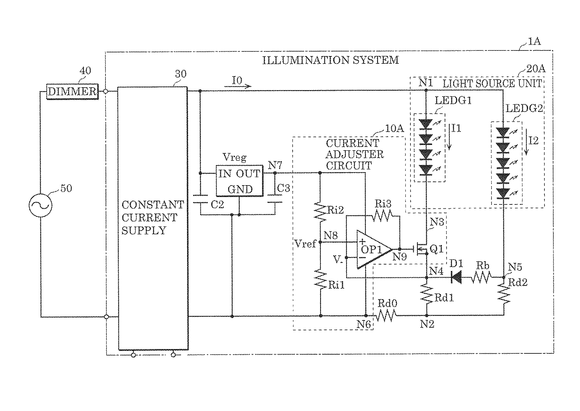
[0043]FIG. 3 is a perspective view of an example of the external appearance of the luminaire in this embodiment. Luminaire 80 illustrated in FIG. 3 is a downlight, and includes circuit box 81, lamp body 82, and wire 83. Circuit box 81 houses circuits (constant current supply, three-terminal regulator, current adjuster circuit, and current detector circuit (not illustrated)) included in luminaire 80. Lamp body 82 houses light source unit 20A. Wire 83 is a wire that connects the circuits and the light source unit included in luminaire 80.

1. Luminaire Configuration

[0044]FIG. 4 is a circuit diagram illustrating an example of the circuit configuration of luminaire 80 in this embodiment. Luminaire 80 is an appliance having a dimming function, and, as illustrated in FIG. 4, includes dimmer 40 and illumination system 1A, and power ...


PUM


Abstract

An illumination system includes: a first light-emitting element column in which one or more first light-emitting elements are serially connected; a second light-emitting element column connected in parallel with the first light-emitting element column, and in which one or more second light-emitting elements are serially connected; a constant current supply that supplies constant current to a light source unit including the first and second light-emitting element columns; a resistor that is connected in series with the first light-emitting element column, and detects magnitude of current flowing through at least the first light-emitting element column; a bypass circuit that passes, to the resistor, at least part of current flowing through the second light-emitting element column, when a predetermined condition is satisfied; and a current adjuster circuit that adjusts the magnitude of the current flowing through the first light-emitting element column, according to the magnitude of the current detected by the resistor.

Description

CROSS REFERENCE TO RELATED APPLICATION[0001]This application claims the benefit of priority of Japanese Patent Application Number 2015-003669 filed on Jan. 9, 2015, the entire content of which is hereby incorporated by reference.BACKGROUND[0002]1. Technical Field[0003]The present disclosure relates to an illumination system and a luminaire using the illumination system.[0004]2. Description of the Related Art[0005]Among conventional luminaires, there are luminaires which include a light source unit having light-emitting elements of plural colors (see, for example, Patent Literature (PTL) 1: Japanese Patent No. 5426802). In the light source unit of the luminaire disclosed in PTL 1, a first light-emitting element column in which first light-emitting elements are connected in series, and a second light-emitting element column in which second light-emitting elements are connected in series, are connected in parallel. A first light-emitting element and a second light-emitting element have...

Claims


Application Information

Patent Timeline
Patent Type & Authority Patents(United States)
IPC IPC(8): H05B33/08H05B44/00
CPCH05B33/0887H05B33/0827H05B33/0851H05B45/24H05B45/50H05B45/44H05B45/46H05B45/10H05B45/345H05B45/31H05B45/14
Inventor SEKI, KEISUKEHIRAMATSU, AKINORIKIDO, HIROSHI
Owner PANASONIC INTELLECTUAL PROPERTY MANAGEMENT CO LTD
Why Eureka
Try Eureka