Surgical implant devices and methods for their manufacture and use
What is AI technical title?
AI technical title is built by Patsnap AI team. It summarizes the technical point description of the patent document.
a technology of implant devices and implants, which is applied in the field of surgical implant devices, can solve the problems that the existing endograft technology does not allow the management of this condition, and achieve the effect of improving in situ accommodation
Active Publication Date: 2017-03-07
EDWARDS LIFESCI CARDIAQ
View PDF450 Cites 23 Cited by
Summary
Abstract
Description
Claims
Application Information
AI Technical Summary
This helps you quickly interpret patents by identifying the three key elements:
Problems solved by technology
Method used
Benefits of technology
Benefits of technology
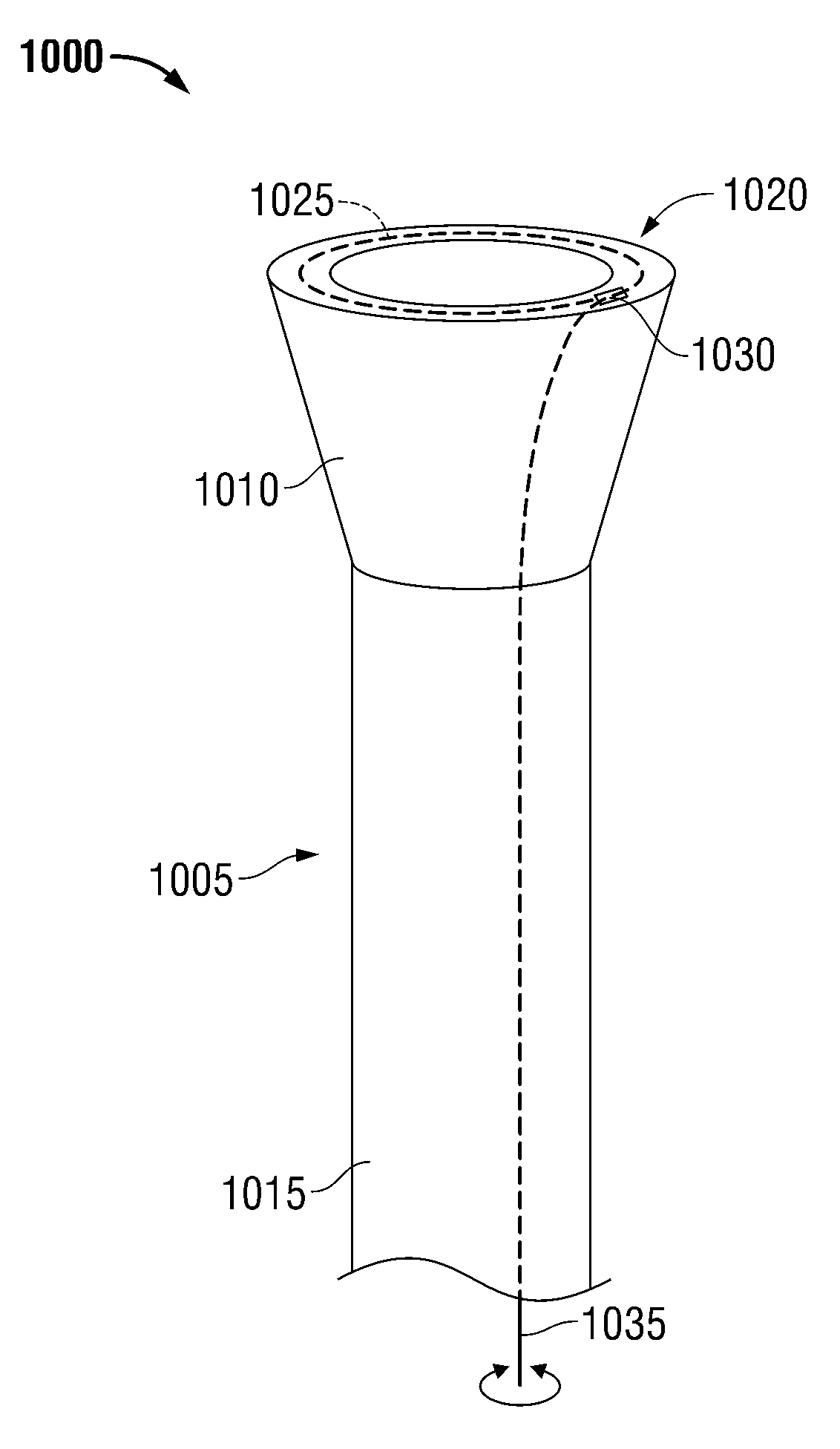
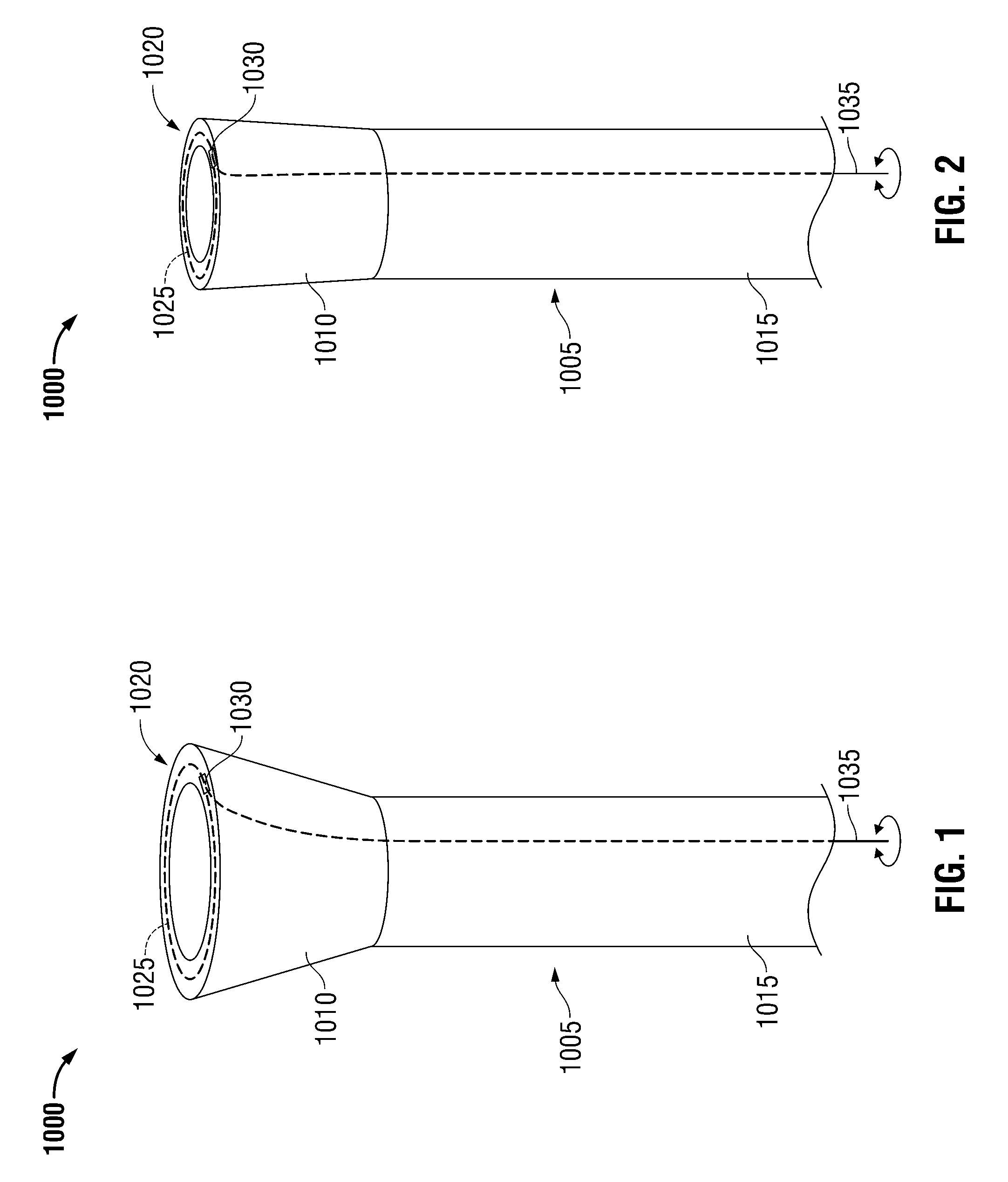
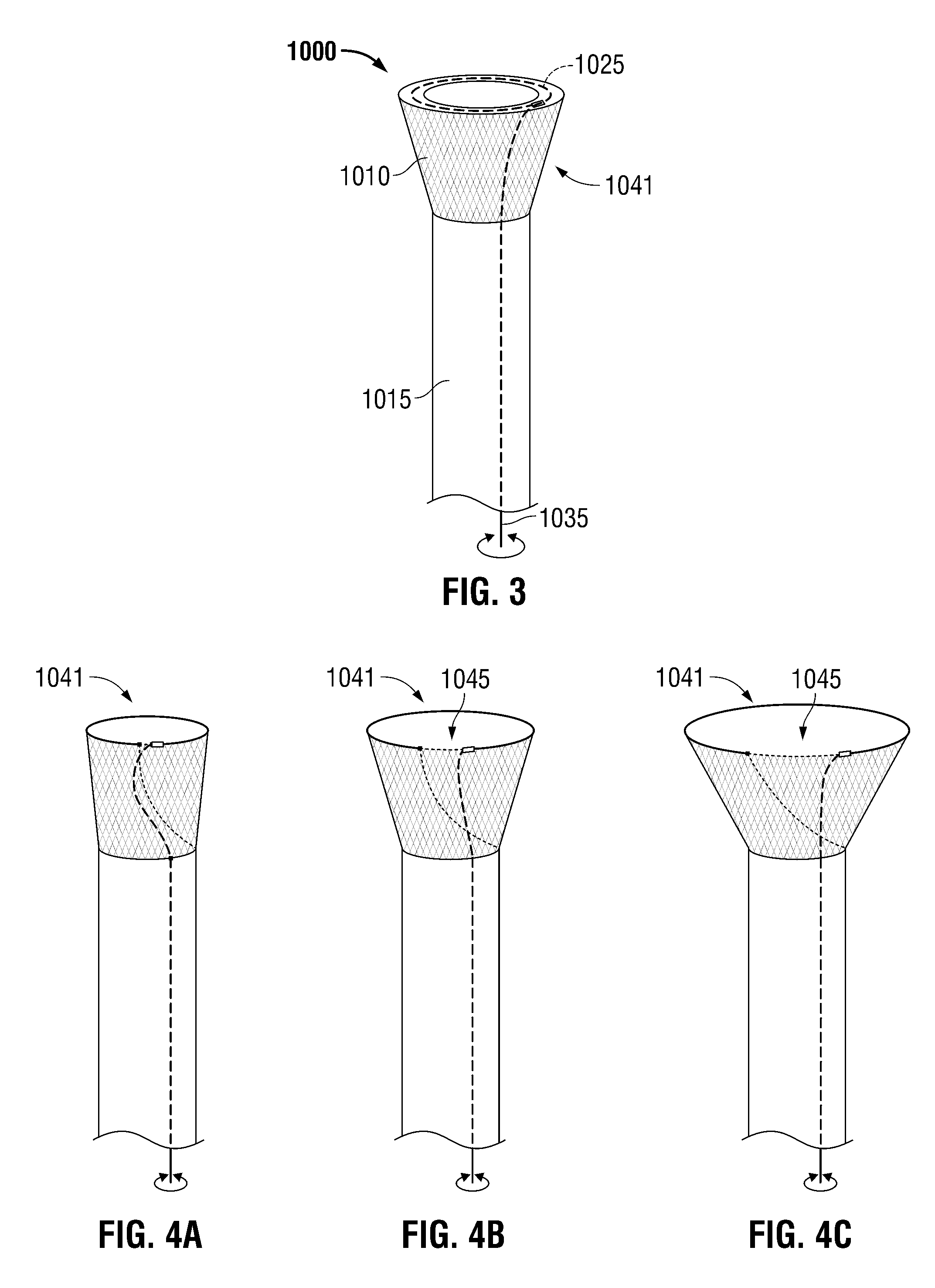
[0017]Exemplary endografts of the present invention as described herein allow for better accommodation by the implant of the local anatomy, using a self-expandable or compressible gasket for the sealing interface between the endograft collar and the recipient vessel's inner wall. Furthermore, exemplary endografts of the present invention as disclosed herein are provided with a controllably releasable disconnect mechanism that allows remote removal of an adjustment tool and locking of the retained sealable mechanism after satisfactory positioning and sealing of the endograft. In some exemplary embodiments according to the present invention, the controllably releasable disconnect mechanism may be provided in a manner that allows post-implantation re-docking of an adjustment member to permit post-implantation repositioning and / or resealing of an endograft subsequent to its initial deployment.
[0018]In other exemplary applications encompassed by the present invention, improved devices for sealing other medical devices such as vascular cannulae may be provided. The present invention further includes novel designs for vascular cannulae to be used when bi-caval cannulation of the heart is indicated, eliminating the need to perform circumferential caval dissection and further reducing the tissue trauma caused by prior art balloon or other bypass cannulae. While the vascular cannulae of the present invention are inserted and positioned by a surgeon in the standard fashion, the need for circumferential dissection of the cavae and tourniquet placement is obviated. After the vascular cannulae of the present invention are positioned and secured with purse string sutures, the surgeon deploys the adjustable sealing devices of the cannulae by turning an adjustment tool or torque wire. Once the sealing devices are deployed, all of the venous return is diverted. The sealing devices deploy around the distal ends of the cannulae and allow blood to flow through the lumen of the cannulae, but not around the sealing devices. Use of these cannulae minimizes the chance of caval injury by eliminating the need for circumferential dissection. Additionally, the configuration of the adjustable sealing device in relation to the cannula is such that the adjustable sealing device is “flush” with the cannula so that no acute change in diameter exists along the external surface of the cannula, which serves to avoid tissue trauma during insertion and withdrawal into and out of bodily structures.
[0019]The present invention addresses several major problems presented by existing designs for balloon cannulae. In various exemplary embodiments according to the present invention, the lumens are configured such that a cannula with an adjustable sealing device can be deployed without compromising either the flow within the principle lumen of the cannula or the seal between the cannula and the structure within which the cannula lies. Moreover, a disclosed example of a cannula according to the present invention is provided with a trough within the cannula body at its distal end in which the adjustable sealing device member lies such that, when undeployed during insertion and withdrawal, there is a smooth interface between the external cannula wall and the undeployed sealing device, allowing for smoother, easier, and safer insertion and withdrawal.
[0020]Moreover, existing designs for balloon cannulae are unable to provide a truly symmetrical placement of an inflated balloon around a central lumen of standard diameter. The asymmetry that results with conventional balloon inflation is sufficient to displace the lumen from the true center of the endovascular lumen in which the balloon cannula is placed, resulting in unpredictable and suboptimal flow characteristics therethrough. The altered hemodynamics of such flow with an existing balloon cannula increases the likelihood of intimal vascular injury and clot or plaque embolization. Vascular cannulae of the present invention achieve the surprising result of having the flow characteristics of a non-balloon cannula by maintaining the preferred laminar flow characteristics of a circular main lumen of consistent diameter, positioned and maintained in or near the center of vascular flow by an adjustable sealing device originally provided within a recessed trough in the exterior wall of the cannula, with accessory lumens contained within an externally circular cannular wall. This allows for better seal, less vascular trauma, and easier vascular ingress and egress.
[0021]In addition, vascular cannulae according to the present invention may be provided with retractable stabilizing elements to anchor the inflated balloon within a vessel lumen during use. Such stabilizing elements further make use of the trough within the cannula body, with the stabilizing elements retracting into this trough during insertion and removal, allowing for smooth and trauma-free entry and egress of the cannula.
Problems solved by technology
While some post-implantation remodeling of the aortic neck proximal to an endovascular graft (endograft) has been reported, existing endograft technology does not allow for the management of this condition without placement of an additional endograft sleeve to cover the remodeled segment.
Method used
Image
Click on the blue label to locate the original text in one second.
Reading with bidirectional positioning of images and text.
Examples
Embodiment Construction
[0070]As required, detailed embodiments of the present invention are disclosed herein; however, it is to be understood that the disclosed embodiments are merely exemplary of the invention, which can be embodied in various forms. Therefore, specific structural and functional details disclosed herein are not to be interpreted as limiting, but merely as a basis for the claims and as a representative basis for teaching one skilled in the art to variously employ the present invention in virtually any appropriately detailed structure. Further, the terms and phrases used herein are not intended to be limiting; but rather, to provide an understandable description of the invention. While the specification concludes with claims defining the features of the invention that are regarded as novel, it is believed that the invention will be better understood from a consideration of the following description in conjunction with the drawing figures, in which like reference numerals are carried forwar...
PUM
Abstract
Sealable and repositionable implant devices are provided with one or more improvements that increase the ability of implants such as endovascular grafts to be precisely deployed or re-deployed, with better in situ accommodation to the local anatomy of the targeted recipient anatomic site, and / or with the ability for post-deployment adjustment to accommodate anatomic changes that might compromise the efficacy of the implant. A surgical implant includes an implant body and a selectively adjustable assembly attached to the implant body, having adjustable elements, and operable to cause a configuration change in a portion of the implant body and, thereby, permit implantation of the implant body within an anatomic orifice to effect a seal therein under normal physiological conditions.
Description
CROSS-REFERENCE TO RELATED APPLICATIONS[0001]This application:[0002]claims the priority, under 35 U.S.C. §119, of U.S. Provisional Patent Application No. 61 / 428,114, filed Dec. 29, 2010;[0003]is a continuation-in-part of co-pending U.S. patent application Ser. No. 11 / 888,009, filed Jul. 31, 2007, now U.S. Pat. No. 8,252,036, which application claims priority to U.S. Provisional Patent Application No. 60 / 834,401, filed Jul. 31, 2006 and 60 / 834,627, filed Aug. 1, 2006; and[0004]is a continuation-in-part of co-pending U.S. patent application Ser. No. 12 / 822,291, filed Jun. 24, 2010, now U.S. Pat. No. 9,408,607, which application claims priority to U.S. Provisional Patent Application No. 61 / 222,646, filed Jul. 2, 2009,the prior applications are herewith incorporated by reference herein in their entireties.STATEMENT REGARDING FEDERALLY SPONSORED RESEARCH OR DEVELOPMENT[0005]Not ApplicableFIELD OF THE INVENTION[0006]The present invention relates to the field of surgical implant devices an...
Claims
Application Information
Patent Timeline
Application Date:The date an application was filed.
Publication Date:The date a patent or application was officially published.
First Publication Date:The earliest publication date of a patent with the same application number.
Issue Date:Publication date of the patent grant document.
PCT Entry Date:The Entry date of PCT National Phase.
Estimated Expiry Date:The statutory expiry date of a patent right according to the Patent Law, and it is the longest term of protection that the patent right can achieve without the termination of the patent right due to other reasons(Term extension factor has been taken into account ).
Invalid Date:Actual expiry date is based on effective date or publication date of legal transaction data of invalid patent.

