High speed high resolution heterodyne interferometric method and system

a heterodyne interferometer and high-resolution technology, applied in the direction of optical radiation measurement, instruments, measurement devices, etc., can solve the problems of limited the typical application of measuring displacement, limited the accuracy and resolution of heterodyne interferometers, and difficult to realize high resolution and high precision displacement measurement, etc., to achieve elimination of frequency and polarization mixing effects, high speed, and the effect of eliminating periodic nonlinearity

Active Publication Date: 2017-03-07
HARBIN INST OF TECH
View PDF4 Cites 2 Cited by
  • Summary
  • Abstract
  • Description
  • Claims
  • Application Information

AI Technical Summary

Benefits of technology

[0030](1) The measurement beam and the reference beam in this method and system are spatially separated, which eliminates the frequency and polarization mixing effects. As a result, the periodic nonlinearity is eliminated.
[0031](2) The measurement signals have opposite Doppler shift for the same target movement. One of the two measurement signals is used selectively according to the direction of the target movement, so that the Doppler shift always increases the beat frequency of the selected signal. As a result, the interferometer can measure a high speed target by using a laser source with low beat frequency.
[0032](3) The measurement circuit can produce high resolution measurements with an ordinary electric clock signal, which make the measurement circuit simple and easy to realize with low cost components.

Problems solved by technology

The periodic nonlinearity caused by frequency and polarization mixing effects limits the accuracy and resolution of a heterodyne interferometer.
A lot of research has been done to reduce the periodic errors, but the traditional heterodyne interferometer can not eliminate the frequency and polarization mixing effects, which make it difficult to realized high resolution and high precision displacement measurement.
But its specific and complicated configuration limits the typically possible applications for measuring displacement.
But the measurement speed is limited by the beat frequency of laser source.
In conclusion, the existing methods and apparatuses described above isn't suitable for high resolution, high speed and high accuracy measurements.

Method used


Image

  • High speed high resolution heterodyne interferometric method and system
  • High speed high resolution heterodyne interferometric method and system

Examples


Embodiment Construction

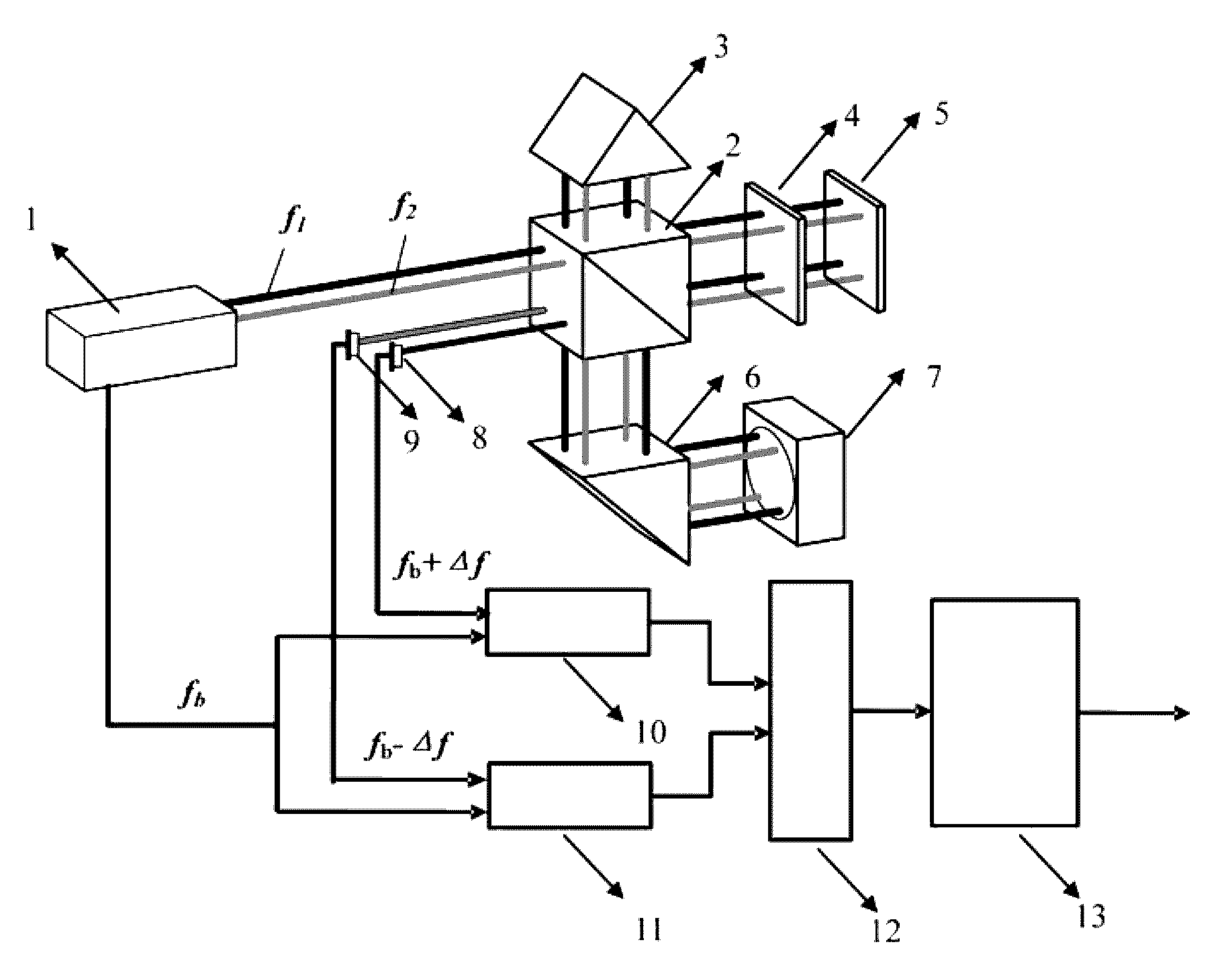
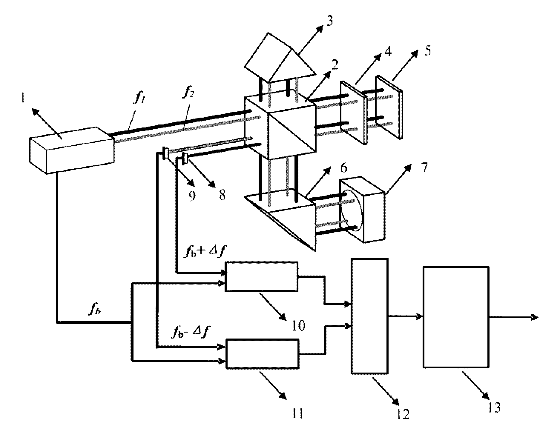
[0036]As shown in the FIGURE, a high speed high resolution heterodyne interferometric system, which comprises: a frequency stabilized laser 1 provided as a light source of the heterodyne interferometric system; a polarizing beam splitter 2 provided to divide the laser beams from said frequency stabilized laser 1; a right angle prism 6 provided to reflect the laser beams reflected by said polarizing beam splitter 2; a reference reflector 7 provided to reflect the laser beams from said right angle prism 6; a quarter wave plate 4 provided to change the polarization of the laser beams transmitted by said polarizing beam splitter 2; a plane mirror 5 provided to reflect the laser beams from the said quarter wave plate 4; a measurement reflector 3 provided to reflect the laser beams reflect by said polarizing beam splitter 2 and placed on the opposite direction of said polarizing beam splitter 2 with respect to right angle prism 6; a photodiode A 8 provided to detect one the measurement be...


PUM


Abstract

A high speed high resolution heterodyne interferometric method and system are provided. The invention uses two spatially separated beams with slightly different frequencies and has two measurement signals with opposite Doppler shift. The switching circuit selects one of the two measurement signals for displacement measurement according to the direction and speed of the target movement. In this invention, the measurement is insensitive to the thermal variation; the periodic nonlinearity is essentially eliminated by using two spatially separated beams; the measurable target speed of the interferometer is no longer limited by the beat frequency of the laser source.

Description

CROSS REFERENCE TO RELATED PATENT APPLICATION[0001]The present application is the US national stage of PCT / CN2012 / 084266 filed on Nov. 8, 2012, which claims the priorities of the Chinese patent applications No. 201210347063.5 filed on Sep. 19, 2012, which applications are incorporated herein by reference.BACKGROUND OF THE INVENTION[0002]Technical Field of the Invention[0003]The present invention relates to a high speed high resolution heterodyne interferometric method and system, which can be used for measuring a high speed target using a laser source with low beat frequency.[0004]Technical Background[0005]The heterodyne interferometer has been widely used in many precision machines and calibration services due to its large measuring range, high signal-to-noise ratio and high measurement precision. Nowadays, high resolution, high speed and high accuracy measurements are required for many applications in order to produce small features with competitive production throughput. This ini...

Claims


Application Information

Patent Timeline
Patent Type & Authority Patents(United States)
IPC IPC(8): G01B9/02G01J9/04G01B11/14G02B27/28
CPCG01B9/02007G01B9/02003G01B9/02027G01B9/02045G01B11/14G01J9/04G01B2290/70G02B27/283
Inventor TAN, JIUBINHU, PENGCHENGDIAO, XIAOFEI
Owner HARBIN INST OF TECH
Why Eureka
Try Eureka