
Modular type cellular antenna assembly

a module-type, cellular antenna technology, applied in the field of antennas, can solve the problems of complex assembly of components, difficult to solder joints, and contribute to phase abnormalities

Active Publication Date: 2017-03-07
COMMSCOPE TECH LLC
View PDF20 Cites 169 Cited by
  • Summary
  • Abstract
  • Description
  • Claims
  • Application Information

AI Technical Summary

Benefits of technology

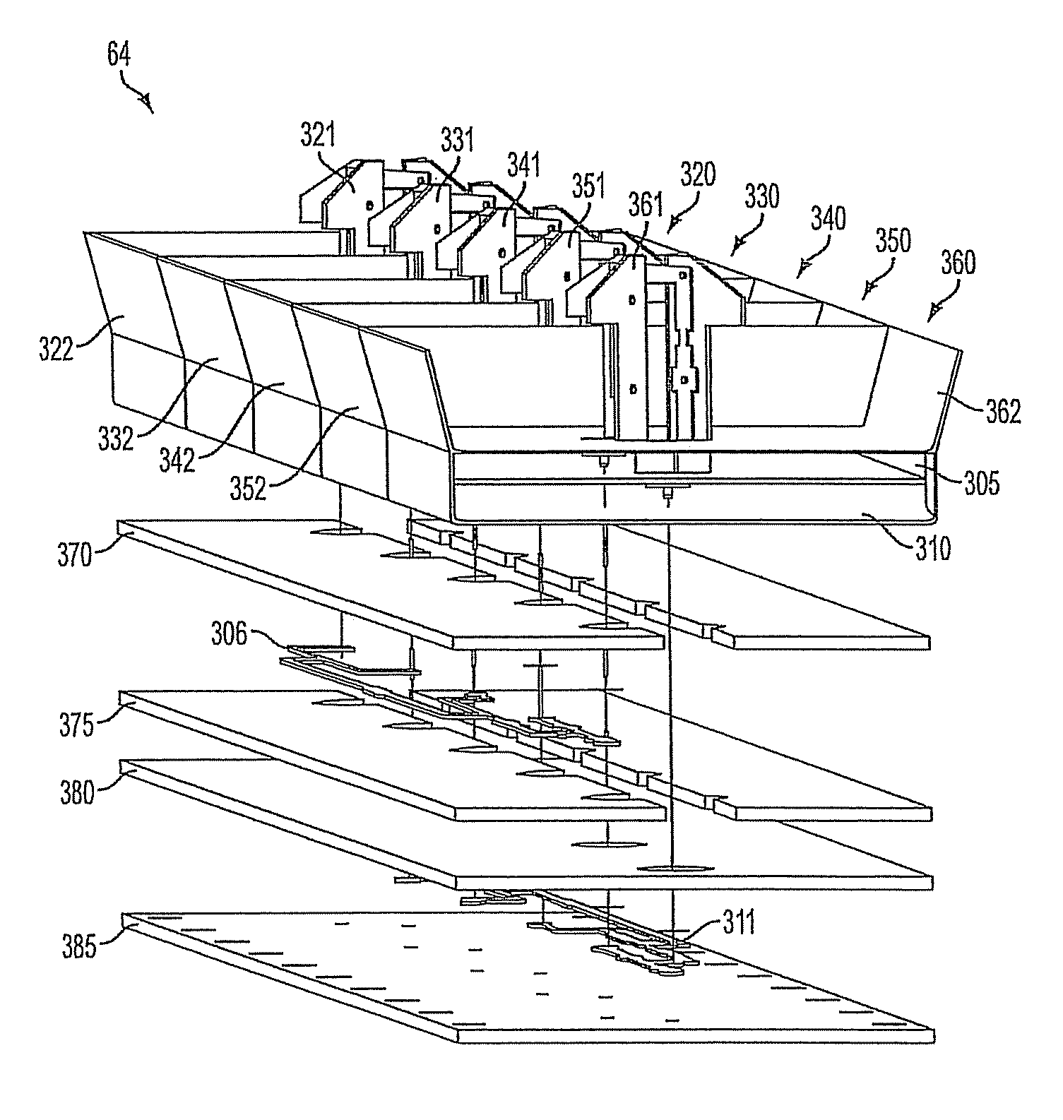
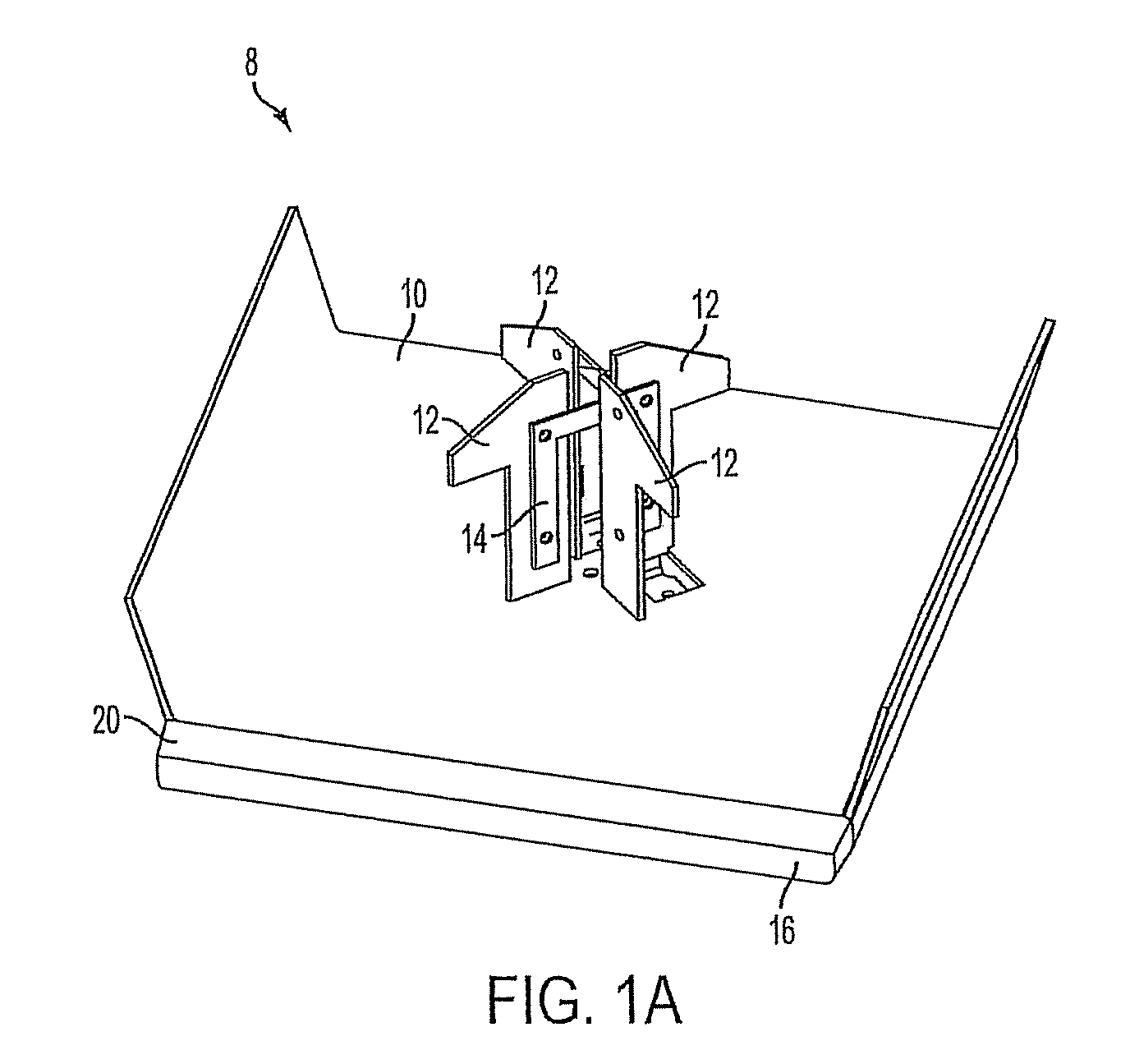
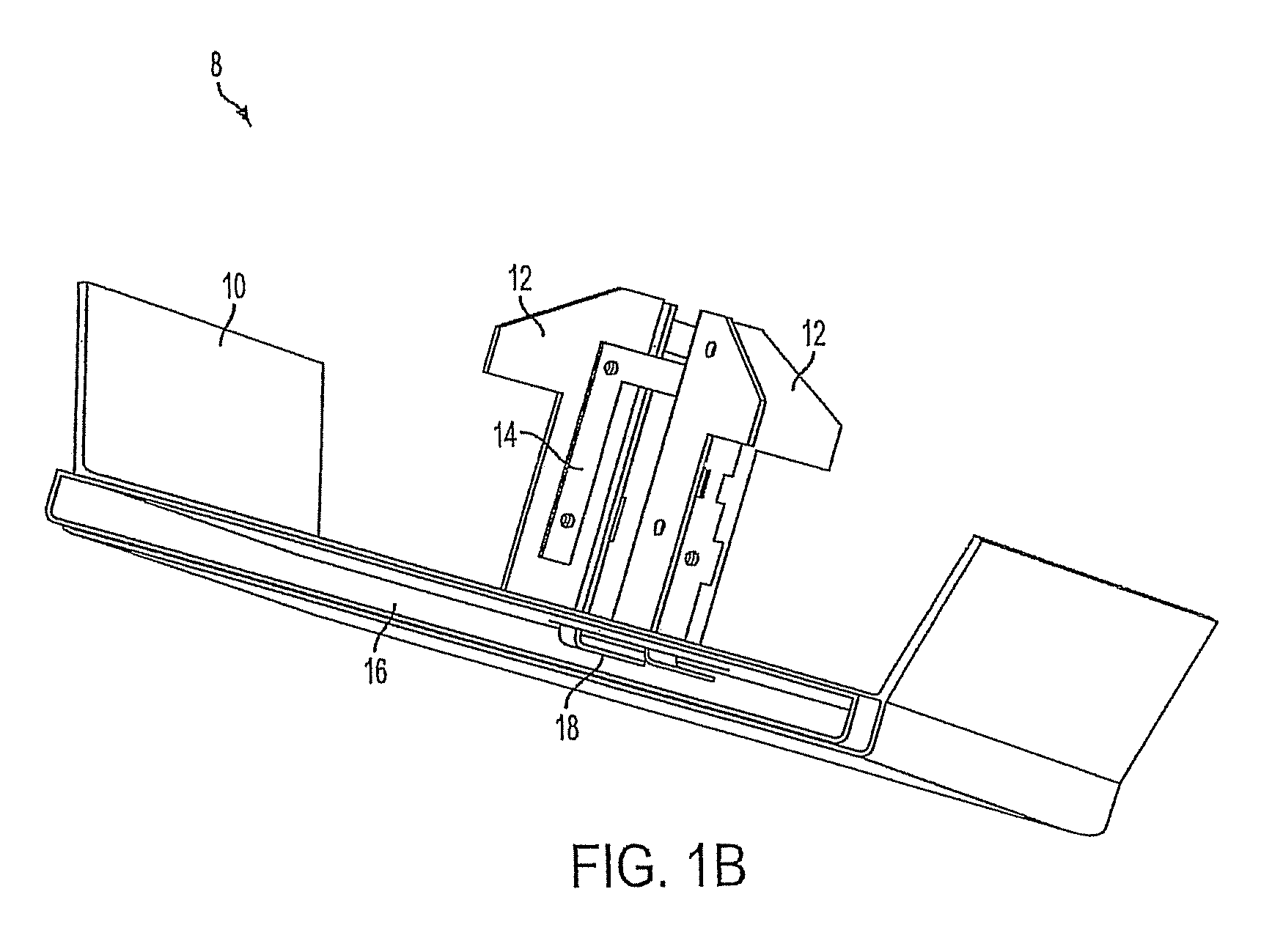
The present invention provides individually formed modular radiating units that can be assembled together to form an antenna array. Each unit includes a reflector, radiating element, and housing for housing a feed network. The housing can form a single chamber or two stacked chambers. The antenna array can also include a junction and one or more phase shift devices. The support structure can mount the antenna array to a vehicle or mount it in a flexible membrane covering. The antenna assembly can also include an RF input connector on the antenna end caps. The technical effects of this invention are improved performance, compact size, and flexibility of the antenna array for various applications.

Problems solved by technology

Known cellular antenna assemblies in mobile communication networks can consist of a single large reflector, feed network, and several radiating elements; these components can be complicated to assemble.
While integrating the radiating elements into the single large reflector is possible in theory, it can be difficult do because of tooling expenses and manufacturing difficulty.
However, because the length of the coaxial cable is not customized for a particular antenna, often radiating elements in the middle of an antenna have excess cable, which must be stowed without violating minimum bend radius requirements.
When soldered connection points are employed, the soldered joints can contribute to phase abnormalities, which are often undesirable.
Furthermore, solder joints can represent additional cost, the potential for error during assembly (e.g., a bad joint), and degradation of the longevity of the antenna panel assembly.
However, when the feed network is not planar, feed lines can get tangled during transportation or handling on the production line.

Method used


Image

  • Modular type cellular antenna assembly
  • Modular type cellular antenna assembly
  • Modular type cellular antenna assembly

Examples


Embodiment Construction

[0029]While this invention is susceptible of an embodiment in many different forms, there are shown in the drawings and will be described herein in detail specific embodiments thereof with the understanding that the present disclosure is to be considered as an exemplification of the principles of the invention. It is not intended to limit the invention to the specific illustrated embodiments.

[0030]Embodiments of the present invention include an antenna assembly formed from a plurality of individually formed radiating units. Each individually formed radiating unit, or RERH unit, can be a modular unit or component and can include housing components and a reflector coupled to a RF radiator element. In some embodiments, multiple radiator elements can be coupled to each reflector.

[0031]Selective coating techniques of conductive coatings, as will be explained herein, can be used to fully integrate a radiating element with a reflector of an individually formed radiating unit. When the radi...


PUM


Abstract

A individually formed radiating unit, an antenna array, and an antenna assembly are provided. The individually formed radiating unit includes a reflector, at least one radiating element integrated into a first side of the reflector, and a housing disposed on a second side of the reflector. The housing forms a chamber for housing a feed network.

Description

CROSS-REFERENCE TO RELATED APPLICATIONS[0001]This application is the national stage of, claims priority to, and incorporates by reference International Application No. PCT / US 10 / 47157 filed Aug. 30, 2010 titled “Modular Type Cellular Antenna Assembly”, which claims priority to and incorporates by reference U.S. Provisional Patent Application No. 61 / 238,588 filed Aug. 31, 2009 and titled “Modular Type Cellular Antenna Assembly.”FIELD OF INVENTION[0002]The present invention generally relates to antennas. More particularly, the present invention relates to an antenna assembly formed from a plurality of individually formed modular radiating units.BACKGROUND[0003]Wireless mobile communication networks continue to evolve given the increased traffic demands on the networks, the expanded coverage areas for service, and the new systems being deployed. Known cellular type communication systems can consist of a plurality of antenna assemblies, each serving a sector or area commonly referred to...

Claims


Application Information

Patent Timeline
Patent Type & Authority Patents(United States)
IPC IPC(8): H01Q15/14H01Q21/08H01Q1/24H01Q21/00H01Q21/26
CPCH01Q21/0025H01Q1/246H01Q15/141H01Q21/08H01Q21/26H01Q9/04H01Q21/00H01Q1/24H01Q1/42H01Q9/0478
Inventor ZIMMERMAN, MARTINVANDERHOOF, TROYBISIULES, PETER
Owner COMMSCOPE TECH LLC
Learn More