Transmission/reception sources of electromagnetic waves for multireflector antenna

a multi-reflector antenna and electromagnetic wave technology, applied in the direction of non-resonant long antennas, differentially interacting antenna combinations, independent non-interacting antenna combinations, etc., can solve the problems of double effect on link budget and increase the level of side lobes, so as to reduce the side lobes of the antenna system

Inactive Publication Date: 2005-03-01
THOMSON LICENSING SA
View PDF3 Cites 163 Cited by
  • Summary
  • Abstract
  • Description
  • Claims
  • Application Information

AI Technical Summary

Benefits of technology

The present invention aims to remedy this problem by providing a T/R source structure having its phase centre between the main reflector and the secondary refle...

Problems solved by technology

However, in reception, the losses of the impressed feed circuit have a double effect on the link budget.
This constraint on the geometry of the Ca...

Method used


Image

  • Transmission/reception sources of electromagnetic waves for multireflector antenna
  • Transmission/reception sources of electromagnetic waves for multireflector antenna
  • Transmission/reception sources of electromagnetic waves for multireflector antenna

Examples


Embodiment Construction

To simplify matters, identical elements bear the same reference numbers in the figures.

Various embodiments of the present invention will now be described with reference to FIGS. 3 to 11.

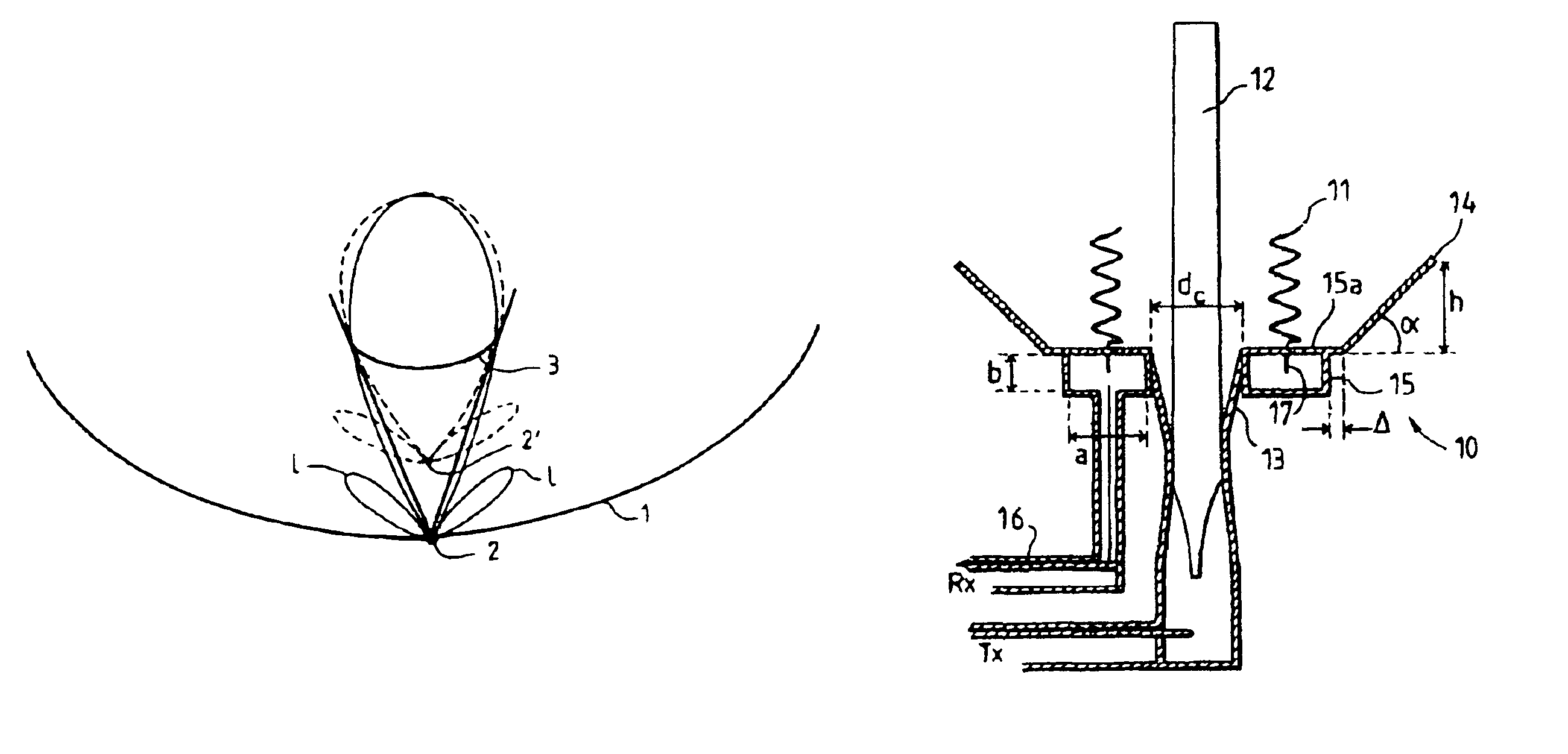
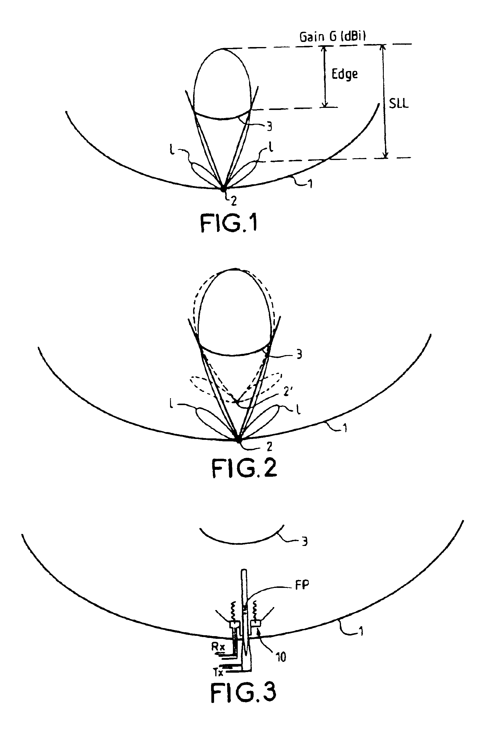
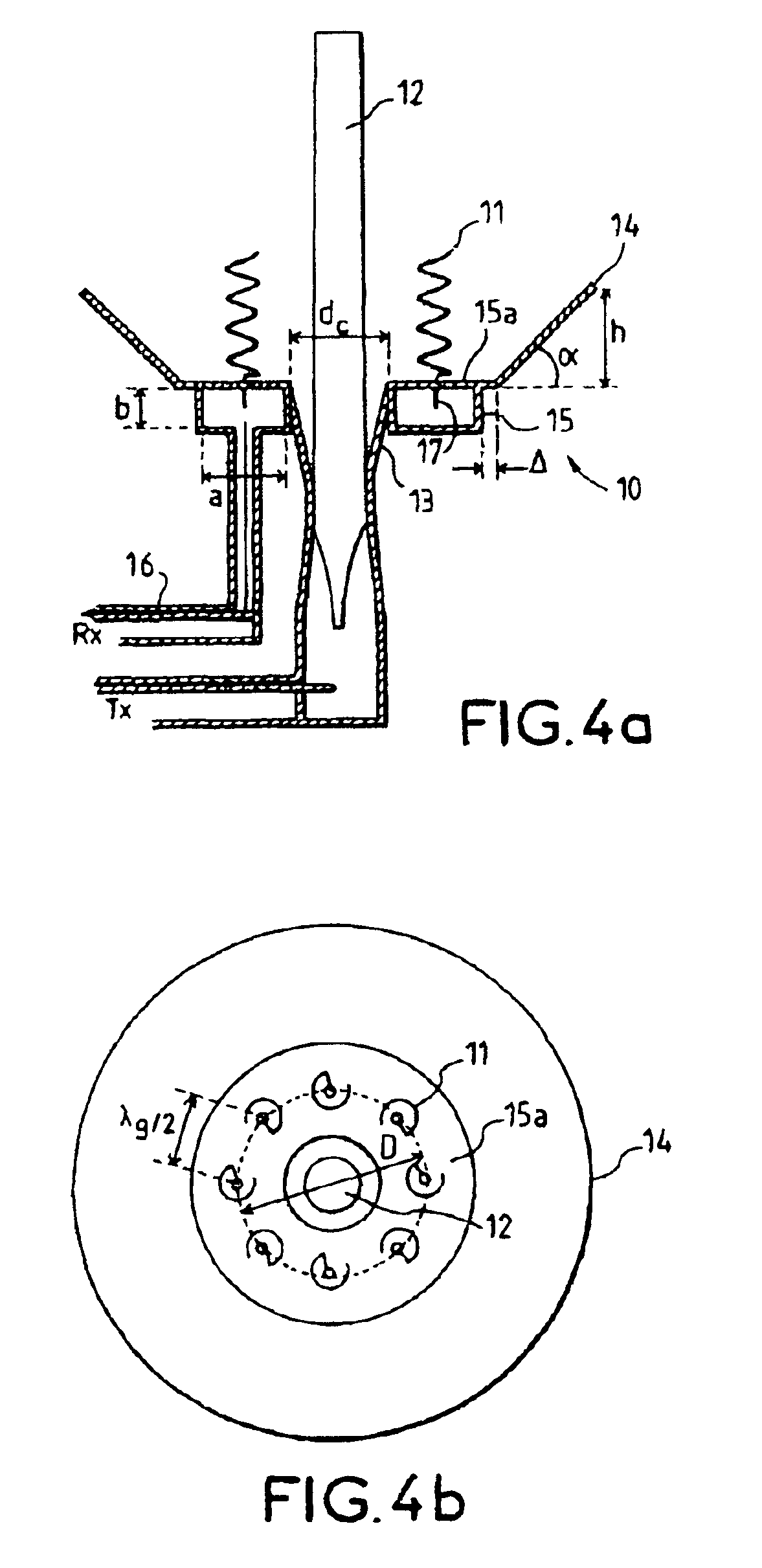
FIG. 3 shows schematically a sectional view of the T / R source 10 forming the subject-matter of the invention, placed at the focal point FP of a double-reflector antenna system located between the two reflectors 1 and 3.

The transmission / reception source antenna forming the subject-matter of the invention benefits, compared with the more conventional solutions using waveguide technology, from the following advantages, namely:reduced size, reduced weight and reduced cost, at the same time as good electrical isolation between the transmission and reception channels thanks to physical isolation between the two channels.

In addition, compared with the system described in French Patent Application 00 / 07424:i) it allows further reduction in the losses of the source consisting of the array of helices, thanks t...


PUM


Abstract

The present invention relates to an electromagnetic wave transmission/reception source for a multireflector antenna of the Cassegrain type comprising longitudinal-radiation means operating in a first frequency band and an array of n radiating elements of the travelling-wave type operating in a second frequency band with the n radiating elements arranged symmetrically around the longitudinal-radiation means, the array and the longitudinal-radiation means having an approximately common phase centre, the array of n radiating elements being excited by a waveguide of polygonal cross section. The invention applies especially in satellite communication systems operating in the C-, Ku- or Ka-bands.

Description

BACKGROUND OF THE INVENTIONThe present invention relates to a transmission (T) / reception (R) source antenna, called hereafter a T / R source, that can be placed at the focal point of an antenna system and more particularly at the focal point of a Cassegrain-type double-reflector antenna. One possible application for this T / R source is in satellite communication systems using the C-, Ku- or Ka-bands.In French Patent Application No. 00 / 07424 filed on Jun. 9, 2000 in the name of Thomson Multimedia, entitled “Perfectionnement aux antennes-source d'émission / réception d'ondes électromagnétiques”, [Improvement to electromagnetic wave transmission / reception source antennas], a hybrid T / R source has been proposed which consists of an array of helices that is excited by an printed feed circuit, surrounding a longitudinal-radiation antenna such as a helix or a “polyrod”.To minimize the interactions between the transmission and reception sources, it is advantageous to use the array of helices for...

Claims


Application Information

Patent Timeline
IPC IPC(8): H01Q5/00H01Q11/08H01Q21/28H01Q13/20H01Q21/00H01Q13/24H01Q11/00H01Q5/45H01Q19/19H01Q5/47H01Q21/29
CPCH01Q11/08H01Q13/24H01Q5/47H01Q5/45H01Q21/28
Inventor LOUZIR, ALIMINARD, PHILIPPETHUDOR, FRANCKPINTOS, JEAN-FRAN.CEDILLA.OIS
Owner THOMSON LICENSING SA
Why Eureka
Try Eureka