Method for modulating color temperature in visible band

a color temperature and visible band technology, applied in the field of modulating color temperatures, can solve the problems of increasing the doubts of experts in various fields about the conformity of reference materials, the difficulty of achieving good color rendering properties in different color temperatures, and the increase of the application of cri

Inactive Publication Date: 2017-03-14
HM ELECTRONICS CO LTD
View PDF3 Cites 6 Cited by
  • Summary
  • Abstract
  • Description
  • Claims
  • Application Information

AI Technical Summary

Benefits of technology

[0006]In view of this, the primary objective of the present invention is to provide a method for modulating colors tem

Problems solved by technology

However, the traditional red, green and blue LEDs usually have narrow spectral bandwidths, and there are only a few kinds of high-efficiency phosphor can work with them.
Under the circumstances that only using three to five different wavelengths to modulate different color temperatures, it is difficult to achieve good color rendering property in different color temperatures.
Although the application of CRI is getting m

Method used


Image

  • Method for modulating color temperature in visible band
  • Method for modulating color temperature in visible band
  • Method for modulating color temperature in visible band

Examples


first embodiment

[0036]In addition, in Step S4, the selected blue, green and red LEDs are identical to those of the first embodiment in terms of quantity and peak wavelength, with the difference that the ratio of the relative intensities of the used two green LEDs (with peak wavelengths as 500 nm and 525 nm) is 5:3, and the ratio of the relative intensities of the used three red LEDs (peak wavelengths as 600 nm, 620 nm and 630 nm) is 4:5:22. The modulated color-temperature curve G is as shown in FIG. 12. It is very close to the target color temperature, 6500K, and thus the cold white light with a color temperature of 6500K can be accurately simulated.

third embodiment

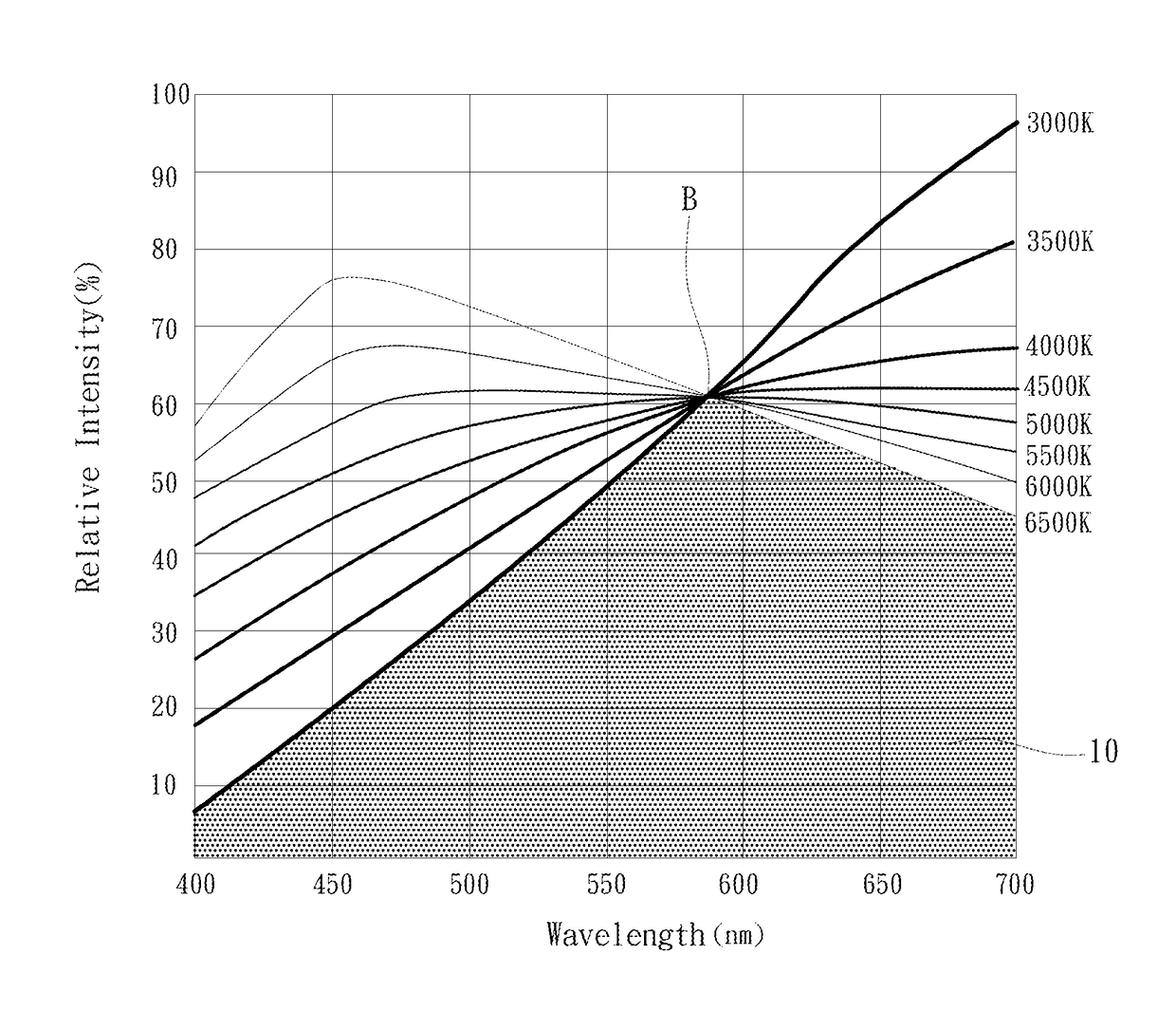
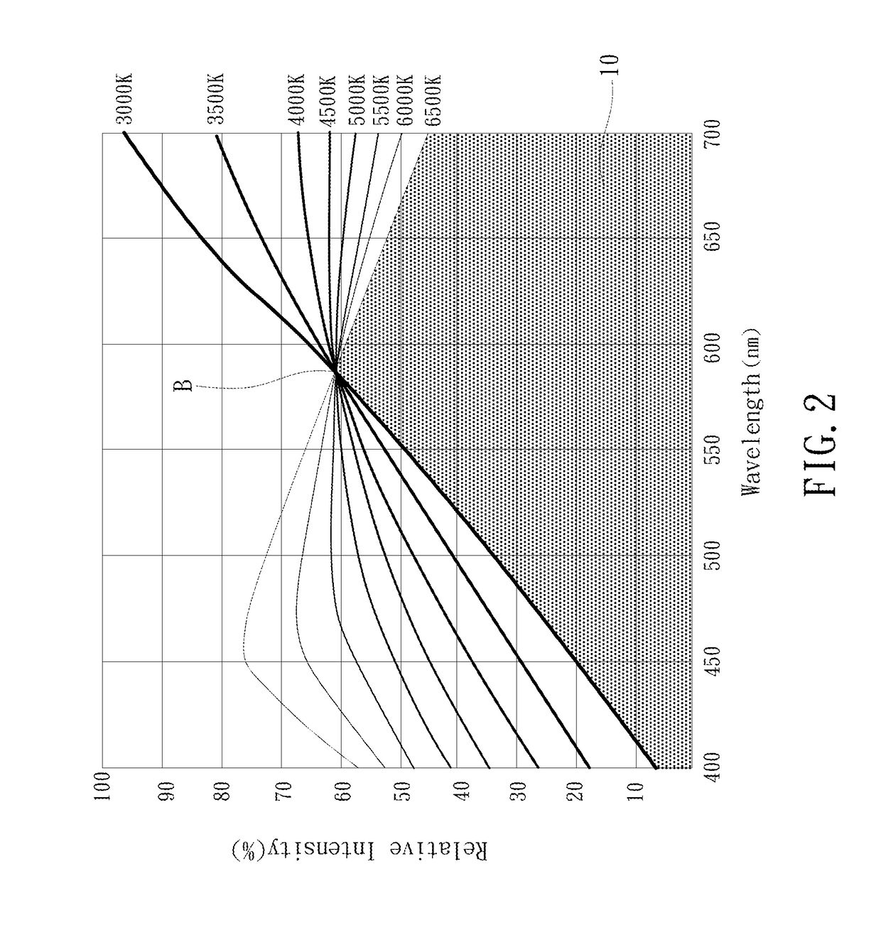
[0037]The present invention further provides a Referring to FIG. 13 and FIG. 14, the present embodiment has normalization performed at the benchmark wavelength B of 570 nm, and has the target color temperature set at 4000K. Also, the primary-peak wavelength 21 of the white LED peak wavelength 20 is close to the benchmark wavelength B (as shown in FIG. 13).

[0038]In a fourth embodiment, the selected blue and green LEDs are identical to those of the first embodiment in terms of quantity and peak wavelength, with the difference that four red LEDs are used, and the peak wavelengths in the red LEDs' spectral curve 51, 52, 53, 54 are 590 nm, 620 nm, 630 nm, and 660 nm respectively.

[0039]The two green LEDs (peak wavelengths at 500 nm and 525 nm) have a ratio between their relative intensities as 5:1, and the ratio of the relative intensities of the four red LEDs (peak wavelengths at 590, 600 nm, 620 nm and 630 nm) is 1:3:3:11. The modulated color-temperature curve G is as shown in FIG. 14,...


PUM


Abstract

A color temperature modulating method involves: computing blackbody spectrums including a target color temperature, and performing normalization at a benchmark wavelength to define a common color-temperature area; selecting a white LED containing phosphor; adjusting the white LED's intensity such that the primary-peak wavelength is close to a maximum relative intensity in the common color-temperature area accordingly; using a blue LED, a green LED, and at least two red LEDs, wherein peak wavelengths of the blue and green LEDs are located between the primary and the secondary wavelength of the white LED, and peak wavelengths of the red LEDs are greater than the primary-peak wavelength; and adjusting relative intensities of the blue, green, and red LEDs to make a relative intensity of a combination of these LEDs and the white LED close to the target color temperature.

Description

BACKGROUND OF THE INVENTION[0001]Technical Field[0002]The present invention relates to methods for modulating color temperatures, and more particularly to a method that uses blackbody radiations as benchmarks to modulate LEDs to simulate specific color temperatures in the visible band, thereby producing light that has good color rendering property.[0003]Description of Related Art[0004]Traditionally, in an adjustable light-emitting device that modulates color temperatures using plural red, green and blue LEDs, adjustment of color temperature is usually achieved according to chromaticity coordinates or CRI (Color Rendering Index). However, the traditional red, green and blue LEDs usually have narrow spectral bandwidths, and there are only a few kinds of high-efficiency phosphor can work with them. Under the circumstances that only using three to five different wavelengths to modulate different color temperatures, it is difficult to achieve good color rendering property in different co...

Claims


Application Information

Patent Timeline
IPC IPC(8): H05B33/08H05B44/00
CPCH05B33/086H05B45/20
Inventor LIN, TSUNG-PING
Owner HM ELECTRONICS CO LTD
Why Eureka
Try Eureka