

Image processing device for correcting image colors and image processing program
a technology for image processing and image colors, applied in the direction of color signal processing circuits, instruments, television systems, etc., can solve problems such as color drift, and achieve the effects of reducing the saturation of input images, detecting or correcting color drift more suitably, and suppressing color structure modification
- Summary
- Abstract
- Description
- Claims
- Application Information
AI Technical Summary
Benefits of technology
Problems solved by technology
Method used
Image

Examples
first embodiment
Description of a Configuration of an Image Processing Device
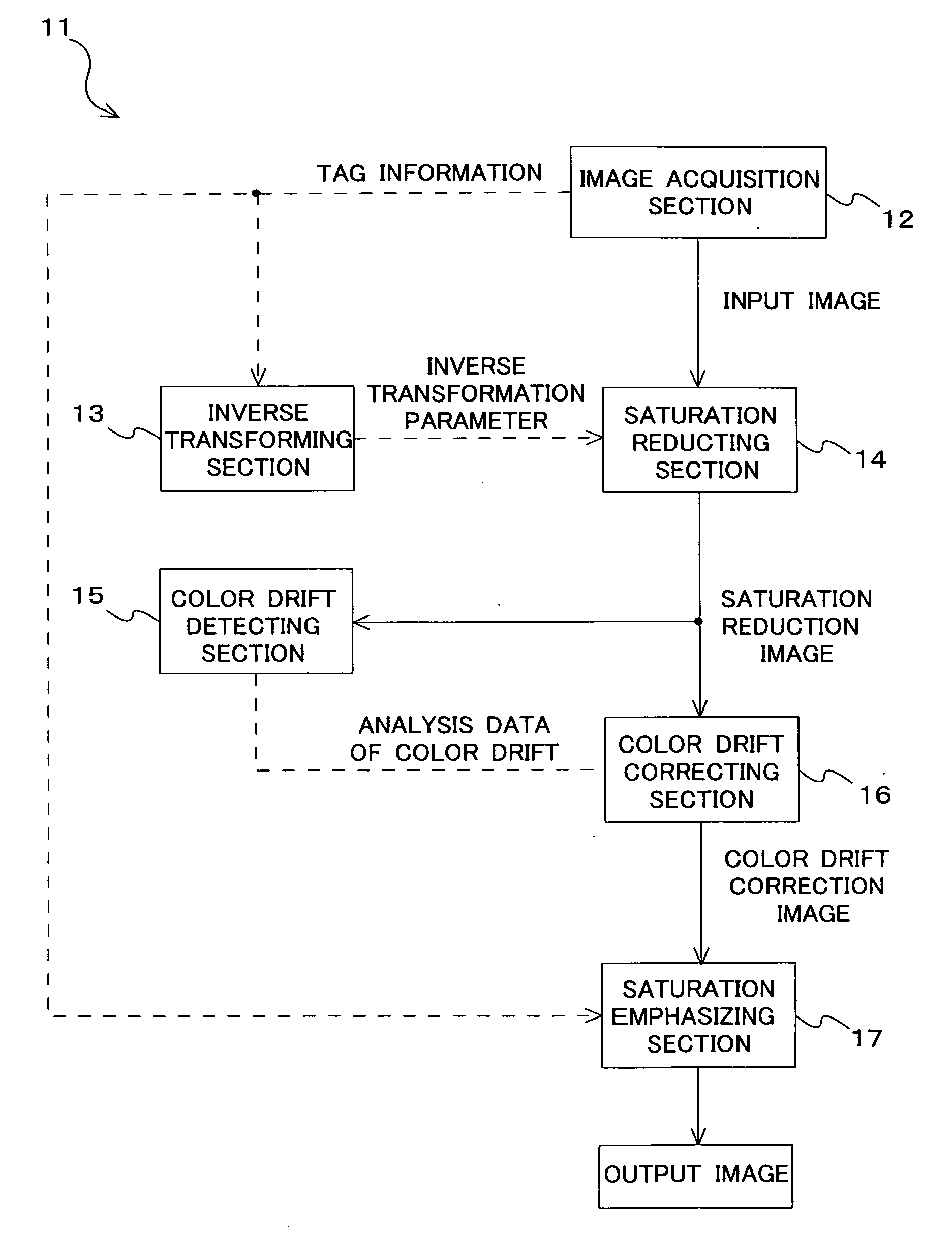
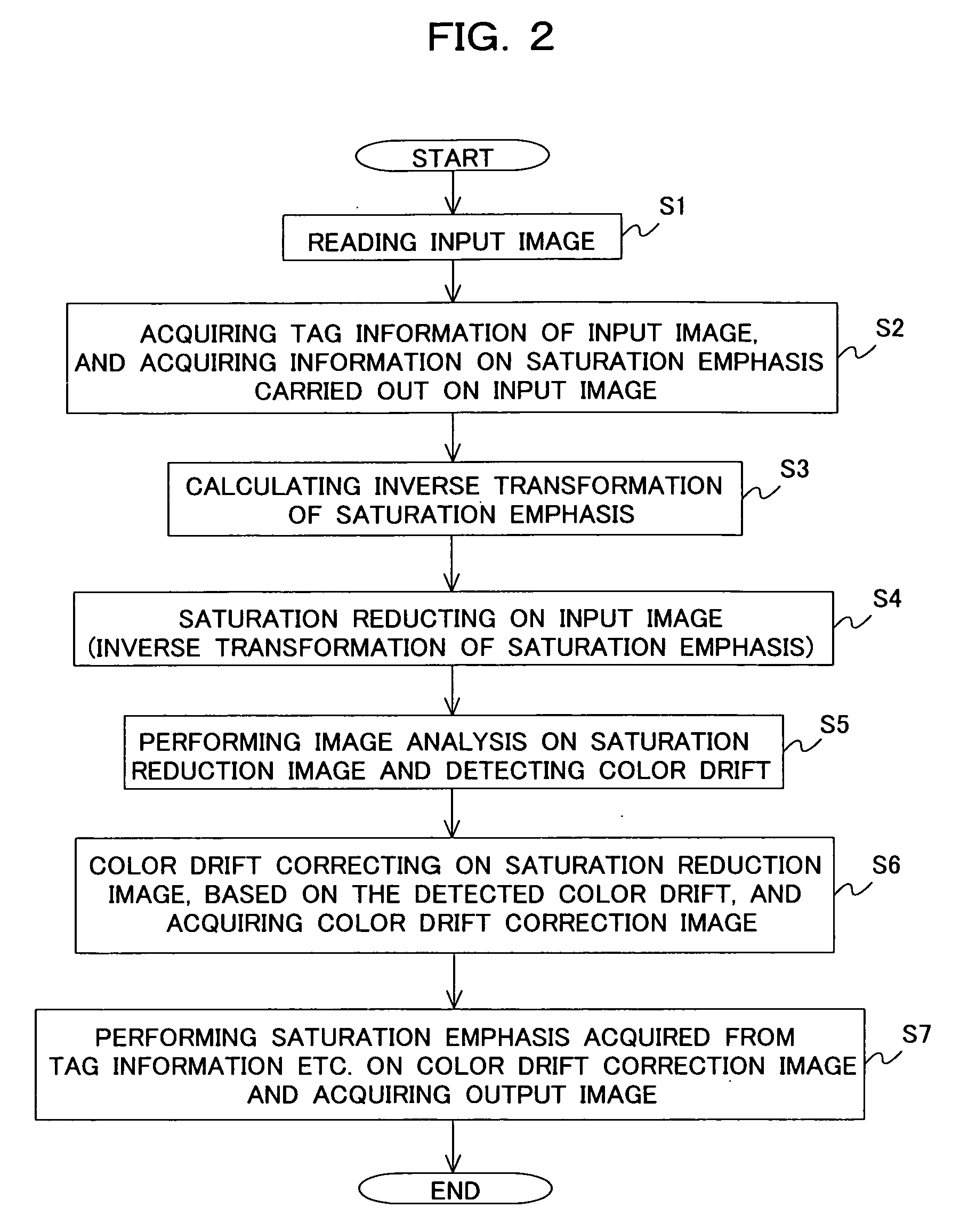
[0031]FIG. 1 is a block diagram showing a configuration of an image processing device 11. In FIG. 1, an image acquiring section 12 stores an input image that is a processing target in an internal memory thereof. An inverse transforming section 13 acquires information on the saturation emphasis performed in advance on the input image, and calculates inverse transformation of the saturation emphasis. A saturation reducing section 14 performs the inverse transformation on the input image and obtains a saturation reduction image. A color drift detecting section 15 detects drift between color components for the saturation reduction image. A color drift correcting section 16 performs color drift correction on the saturation reduction image according to information on the color drift. A saturation emphasizing section 17 again performs saturation emphasis comparable to that of the input image on the image after color drift correcti...
second embodiment
[0058]FIG. 9 is a view describing operation of a second embodiment. In addition, since a configuration of a device according to the second embodiment is the same as that (FIG. 1) of the first embodiment, description thereof will be eliminated here.
[0059]Generally, for internal processing of an electronic camera, as shown in FIG. 9, in some cases, multiple times of saturation emphasis are performed on a picked-up image. Here, the multiple times of saturation emphasis are performed in the following order.
[0060](1) First saturation emphasis by saturation emphasizing transformation matrix M1
[0061](2) Tone conversion for each color component by gamma transformation G(x)
[0062](3) Second saturation emphasis by saturation emphasizing transformation matrix M2
[0063]The inverse transforming section 13 reads tag information (such as EXIF information) from the inside of the file of an input image. Information on the above-mentioned image processing (M1, G(x), M2) are stored on the tag informatio...
third embodiment
[0078]FIG. 10 is a flow chart showing operation of a third embodiment.
[0079]In the third embodiment, a case in which the inverse transformation of saturation emphasis is approximately calculated will be described. In addition, since the device configuration of the third embodiment is the same as that (FIG. 1) of the first embodiment, duplicated description thereof will be eliminated here.
[0080]First, a plurality of color components Si=(RSi, GSi, BSi) are defined in advance. For example, 83=512 kinds of color components Si=(RSi, GSi, BSi) can be defined by the change of the color components RSi, GSi, and BSi into eight kinds, respectively. For example, when each color component is 12 bits tone, eight kinds of color components are set to be the values of [0, 512, 1024, 1536, 2048, 2560, 3072, 3584].
[0081]For these color components Si, the following two kinds of image processing are tried at the side in the electronic camera.
[0082](1) Image processing (including saturation emphasis) pe...
PUM
 Abstract
Description
Claims
Application Information