
Base station, mobile communication system, and communication method

a mobile communication system and base station technology, applied in the field of base station, mobile communication system, communication method, to achieve the effect of reducing the equipment scale of a base station

Inactive Publication Date: 2006-08-29
NTT DOCOMO INC
View PDF10 Cites 29 Cited by
  • Summary
  • Abstract
  • Description
  • Claims
  • Application Information

AI Technical Summary

Benefits of technology

[0015]The object of the present invention is to enable a mobile station to receive signals appropriately, and reduce the equipment scale of a base station.
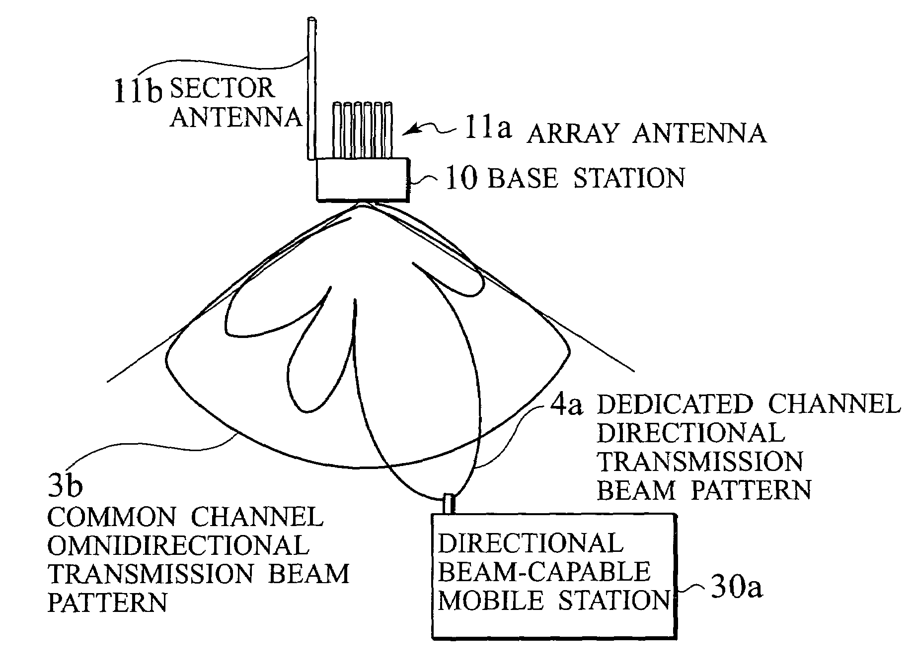
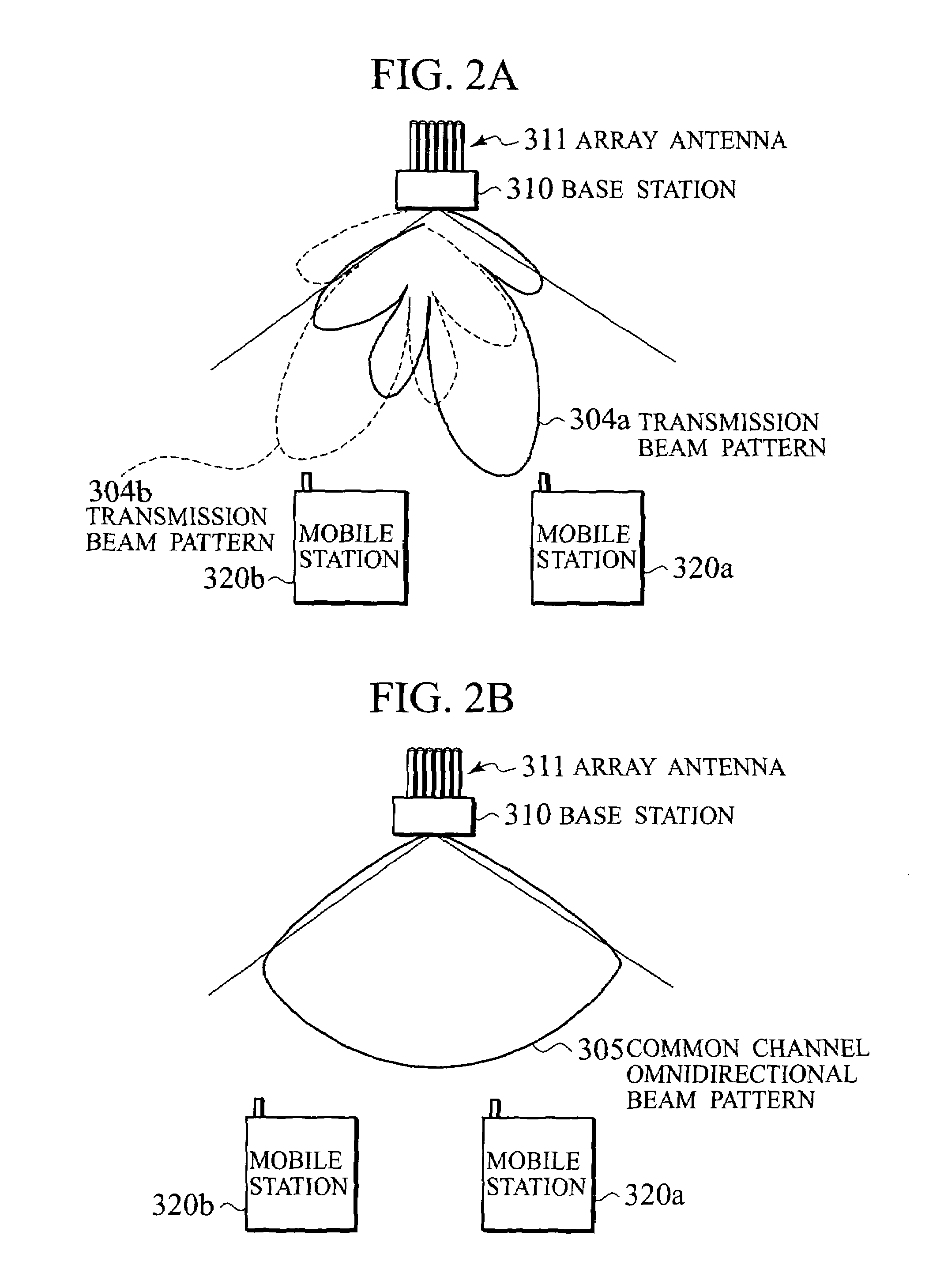
[0018]More specifically, the base station can transmit a dedicated channel to the mobile station capable of receiving a directional beam with a directional beam, by using the directional antenna. Accordingly, the base station can improve beam gain, and the saturation power of the transmission amplifier can be reduced. In addition, the base station can transmit the dedicated channel to the mobile station incapable of receiving a directional beam with an omnidirectional beam, by using the omnidirectional antenna. Accordingly, the base station can prevent an increase in the saturation power of the transmission amplifier when transmitting the omnidirectional beam using the directional antenna as with the first conventional method and the second conventional method. As a result, the equipment scale of the base station may be reduced.
[0020]According to the communication method, to begin with, the base station determines whether or not the mobile station is capable of receiving a directional beam. The base station then selects the directional antenna as an antenna to be used for transmitting the individual data when the mobile station is capable of receiving a directional beam, and transmits the individual data to the mobile station. Meanwhile, the base station selects the omnidirectional antenna as an antenna to be used for transmitting the individual data when the mobile station is incapable of receiving a directional beam, and transmits the individual data to the mobile station. Accordingly, the base station can switch the antenna to be used for transmitting the individual data according to the type of mobile station. As a result, the base station may transmit signals appropriately, according to the type of mobile station, and the mobile station may receive signals appropriately. Furthermore, the base station can prevent an increase in the saturation power of the transmission amplifier when transmitting the omnidirectional beam using the directional antenna as with the first or the second conventional method. As a result, the equipment scale of the base station may be reduced.

Problems solved by technology

In addition, the base station can transmit the dedicated channel to the mobile station incapable of receiving a directional beam with an omnidirectional beam, by using the omnidirectional antenna.

Method used


Image

  • Base station, mobile communication system, and communication method
  • Base station, mobile communication system, and communication method
  • Base station, mobile communication system, and communication method

Examples


first embodiment

[First Embodiment]

(Mobile Communication System)

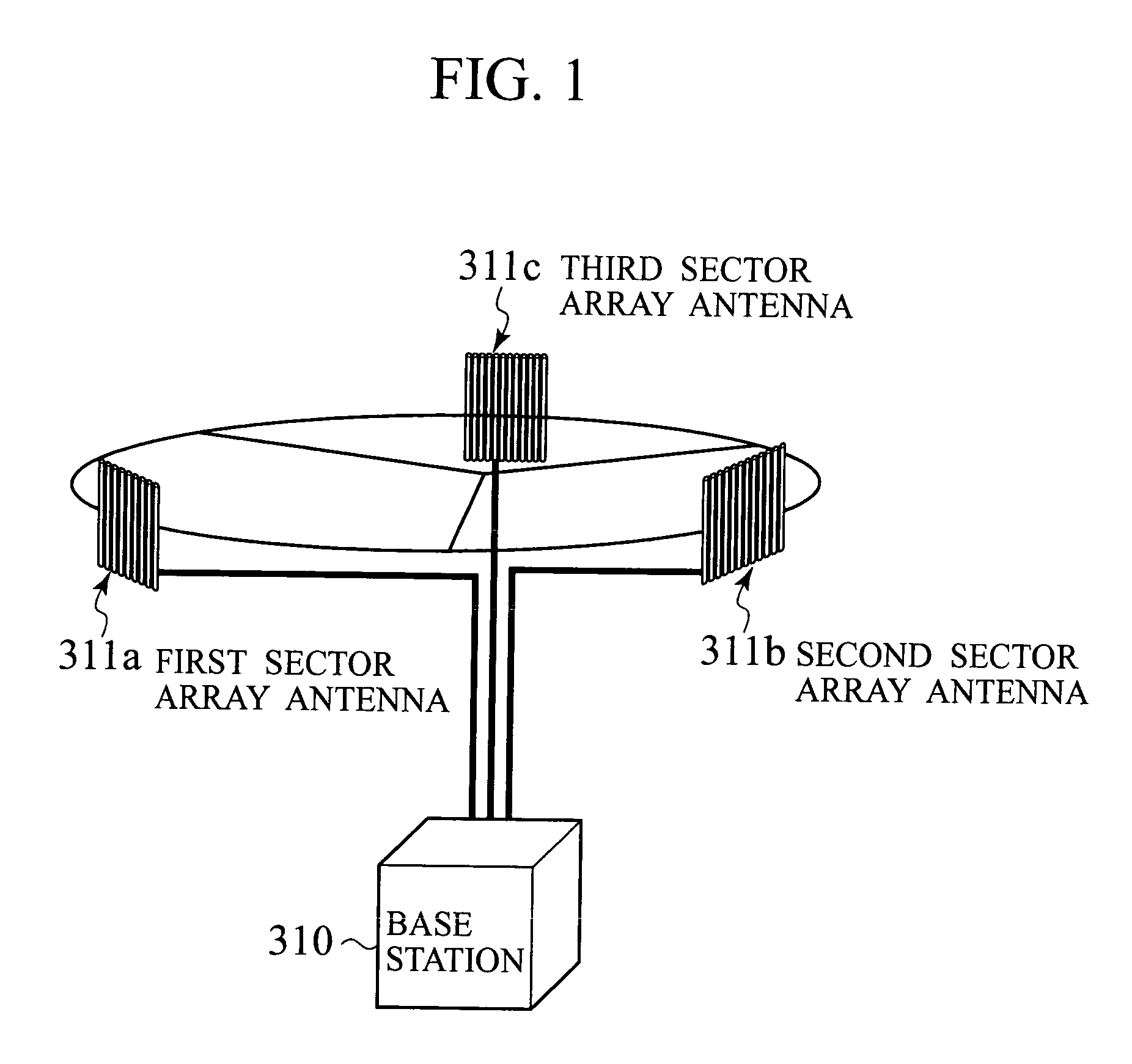
[0034]As shown in FIGS. 3A and 3B, a mobile communication system adopts a sector-cell structure that covers a service area by dividing a cell 1 into a plurality of sectors and placing for each sector on a base station 10. As the sector-cell structure, there is a three-sector structure as shown in FIG. 3A where the cell 1 is divided into three sectors, a first sector 1a, a second sector 1b, and a third sector 1c; and a six-sector structure as shown in FIG. 3B where the cell1 is divided into six sectors, a first sector 1a, a second sector 1b, a third sector 1c, a fourth sector 1d, a fifth sector 1e, and a sixth sector 1f. A mobile communication system adopting the three-sector structure is described below, as an example.

[0035]As shown in FIG. 4, a mobile communication system 100 comprises a base station 10, a radio network control equipment 20, and a plurality of mobile stations 30. The base station 10 connects radio links with the mobile...

second embodiment

[Second Embodiment]

(Mobile Communication System)

[0074]A mobile communication system 200 adopting the three-sector structure shown in FIG. 3A is described below, as an example. As shown in FIG. 9, a mobile communication system 200 comprises a base station 210, a radio network control equipment 20, and a plurality of mobile stations 230. The base station 210 comprises a first sector array antenna 211a1, a first sector sector antenna 211b1, and a first sector sector antenna 211c1, which cover the first sector 1a; a second sector array antenna 211a2, a second sector sector antenna 211b2, and a second sector sector antenna 211c2, which cover the second sector 1b; and a third sector array antenna 211a3, a third sector sector antenna 211b3, and a third sector sector antenna 211c3, which cover the third sector 1c.

[0075]As shown in FIG. 9, the number of the sector antennas for each sector is two, that is, the base station 210 comprises a plurality of sector antennas. When DS-CDMA is adopted...

modified example

[0111]The present invention is not limited to the described above first and second embodiments, and various modifications are possible. The base stations 10 and 210 shown in FIG. 4 and FIG. 9 have the same antenna configuration for all of the first sector 1a through third sector 1c, but are not limited thereto. For example, the base stations 10 and 210 may have a different antenna configuration for each sector, according to the propagation environment surrounding the base stations 10 and 210 and the arranging environment of the base stations 10 and 210, array antennas, and sector antennas.

[0112]In addition, the base station 10 shown in FIG. 5 may perform antenna diversity reception of signals from the mobile stations 30 by using the array antenna 11a and the sector antenna 11b. In this case, the base station 10 must have an array antenna weight controller, an array antenna combiner, a demodulator for the array antenna 11a, and a combiner as shown in FIG. 12, in addition to the demod...


PUM


Abstract

A base station comprises a directional antenna configured to transmit a directional beam to a mobile station, an omnidirectional antenna configured to transmit an omnidirectional beam to the mobile station, and an antenna controller configured to determine whether or not the mobile station is capable of receiving the directional beam, and select the directional antenna as an antenna for transmitting individual data in a case of being capable of receiving the directional beam, or select the omnidirectional antenna as an antenna for transmitting the individual data in a case of being incapable of receiving the directional beam.

Description

CROSS REFERENCE TO RELATED APPLICATIONS[0001]This application is based upon and claims the benefit of priority from the prior Japanese Patent Application No. P2002-244281, filed on Aug. 23, 2002; the entire contents of which are incorporated herein by reference.BACKGROUND OF THE INVENTION[0002]1. Field of the Invention[0003]The present invention relates to a base station, a mobile communication system, and a communication method.[0004]2. Description of the Related Art[0005]Conventionally, a mobile communication system adopts a cellular system, which covers service areas two-dimensionally by arranging a plurality of base stations to form a plurality of cells. In addition, the mobile communication system adopts a sector-cell structure that covers the service area by dividing a cell into a plurality of sectors and placing antennas for each sector on the base stations. In the mobile communication system, directional beam reception / transmission techniques using adaptive antenna array div...

Claims


Application Information

Patent Timeline
Patent Type & Authority Patents(United States)
IPC IPC(8): H04M1/00H04B7/06H04B7/08H04B7/26H04W16/28
CPCH04W16/28H04B7/06
Inventor OKAWA, KOICHITANAKA, SHINYANAKAMURA, TAKEHIRO
Owner NTT DOCOMO INC
Learn More