Combined miscible drive for heavy oil production

a technology of heavy oil and combined drive, which is applied in the direction of fluid removal, chemistry apparatus and processes, and wellbore/well accessories, etc., can solve the problems of hydro cracking of asphaltene fraction, steam injection process heat loss to the upper and lower layers surrounding the target formation, and the economic undesirable effect of steam-flooding heavy oil formations

Inactive Publication Date: 2009-07-16
LEGACY ENERGY
View PDF48 Cites 32 Cited by
  • Summary
  • Abstract
  • Description
  • Claims
  • Application Information

AI Technical Summary

Benefits of technology

[0020]The foregoing needs are met for teriary production of heavy oil formations, to a great extent, by certain embodiments of the present invention. According to one such embodiment, a method of oil production is provided. The method includes drilling an injection well and a production well in the target oil formation. The method also includes pumping a mixture of oxygen, carbon dioxide (CO2) and a foaming agent into the injection well. In addition, the method also includes minimizing gravity segregation by providing a relatively high level of CO2 in the gas mixture and soluble salt in the aqueous phase.

Problems solved by technology

Steam injection processes typically suffer from heat losses to the upper and lower layers surrounding the target formation.
Thus, steam-flooding heavy oil formations usually become economically undesirable at depths greater than approximately 4500 ft.
The heat from contact with the hot gases reduces the viscosity of the heavy oil, vaporizes the light hydrocarbon fraction in the heavy oil and connate water, and causes some hydro cracking of the asphaltene fraction.
Also, the heavier oil fraction pyrolyzes, resulting in the formation of methane, heavier hydrocarbon gases and solid organics that deposit thick residuum behind of the cracking / vaporization zone.
The chemical reactions associated with ISC process are typically complex and numerous.
These reactions increase the heavy oil viscosity and can reduce the sweep efficiency of the combustion flood.
Typically, ISC processes have poor vertical conformance in a layered formation due to the high mobility ratio between hot combustion gases and cold heavy oil.
In such instances, the intense heat then melts the casing and destroys the well.
In spite of these advantages, the wet combustion process encounters liquid-blocking problems.
More specifically, at the burn front, some regions of the burn front drop into medium or low temperature combustion temperatures due to the high water-oxygen gas ratio drowning the combustion front.

Method used


Image

  • Combined miscible drive for heavy oil production
  • Combined miscible drive for heavy oil production
  • Combined miscible drive for heavy oil production

Examples


Embodiment Construction

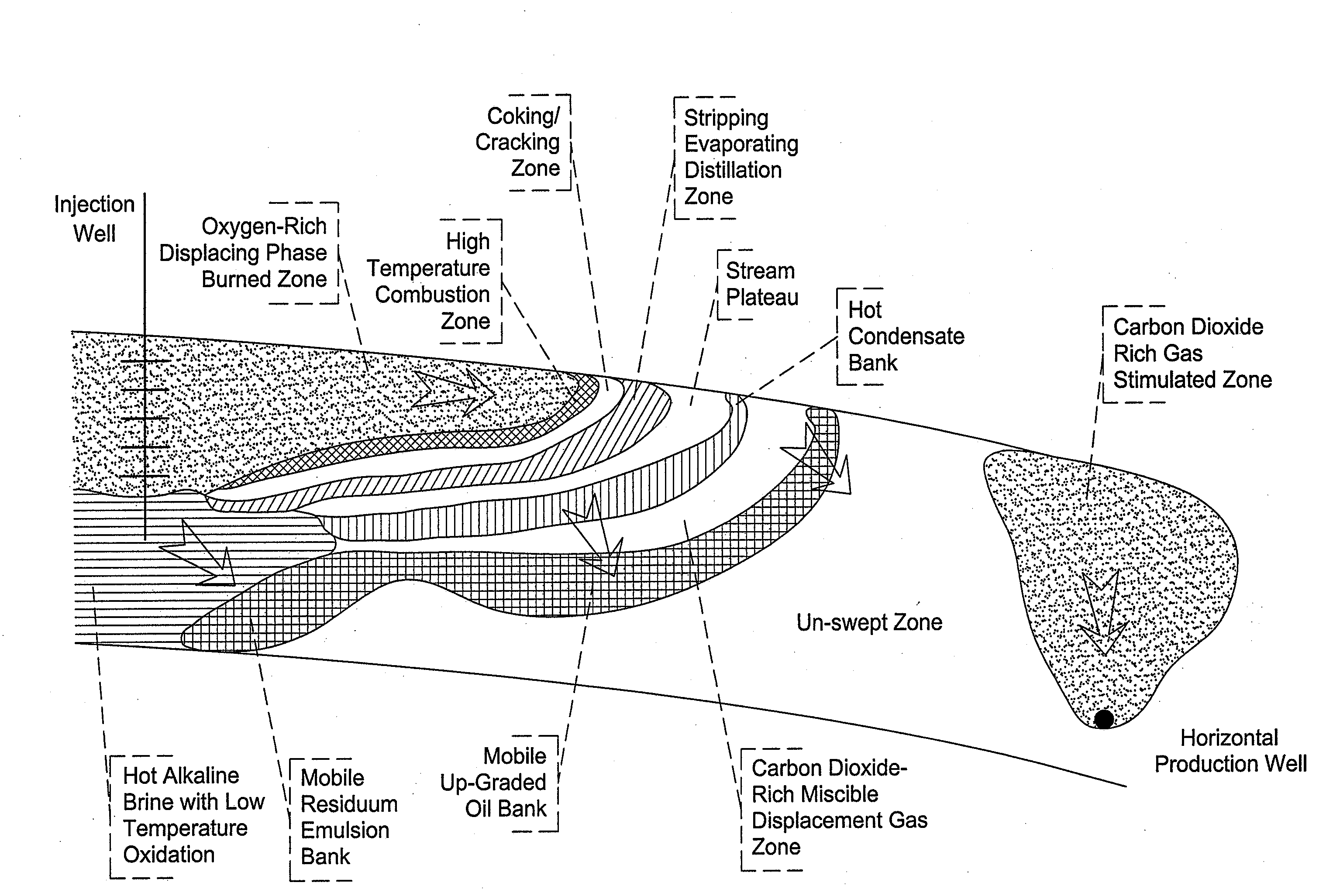
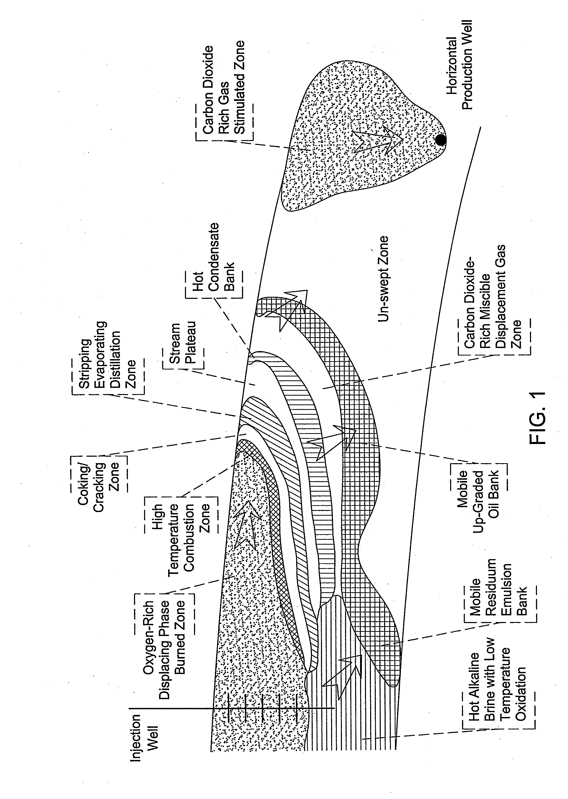
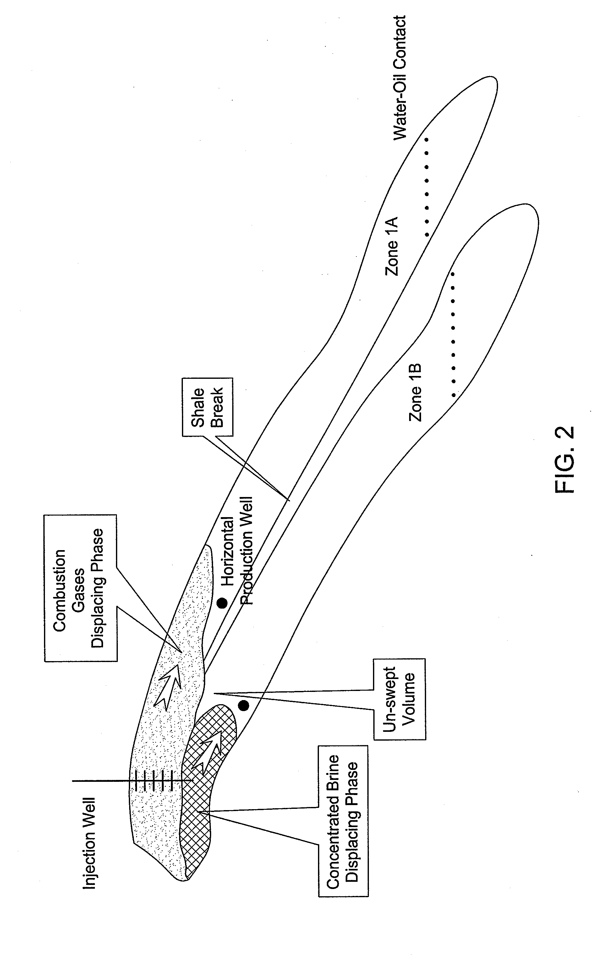
[0038]The invention will now be described with reference to the drawing figures, in which like reference numerals refer to like parts throughout. Combined miscible displacement is an in-situ wet combustion technique in which an aqueous surfactant solution is pumped simultaneously with near-pure oxygen gas into the formation as foam. According to this technique, a high-temperature foaming agent is typically used to prevent the gravity segregation of water from the oxygen gas and to provide mobility control with heavy oil formations.

[0039]Wet foam forward combustion was developed to recover the great amount of heat that would otherwise be lost to heat transfer to the surrounding layers bounding the target formation. The foam promotes uniform burning along the combustion front in a formation with variable permeability in the horizontal and vertical directions. As the water evaporates from the foam, the quality of the foam increases until it reaches about 90%. Then, the foam breaks and ...


PUM


Abstract

A method of oil production is provided. The method includes forming an injection well and a production well. The method also includes pumping a mixture of oxygen and carbon dioxide (CO2) into the injection well. In addition, the method also includes minimizing gravity segregation by providing a relatively high level of CO2 in the mixture.

Description

FIELD OF THE INVENTION[0001]The present invention relates generally to devices and methods for oil extraction. More particularly, certain embodiments of the present invention relate to devices and methods for extracting heavy oil.BACKGROUND OF THE INVENTION[0002]In order to extract maximum amount of oil from the earth, at least one injection well and several production wells are typically drilled into the target oil formation (e.g., an oil reservoir). Typically, water is pumped into the injection well to displace low-viscosity oil from the target formation to the production well. After water-flooding the target formation, the residual oil saturation ranges from 30% to 50%, depending on the oil-water mobility ratio. To reduce the residual oil saturation to below 20%, steam, miscible gas or a surfactant solution is pumped into the injection well to flood the target formation to the production wells.[0003]Because of their inherent high viscosities, tars and heavy oils can not be displa...

Claims


Application Information

Patent Timeline
Patent Type & Authority Applications(United States)
IPC IPC(8): E21B43/22
CPCE21B43/243
Inventor FRAIM, MICHAEL
Owner LEGACY ENERGY
Why Eureka
Try Eureka