Dynamic pressure method of detecting flame on/off in gas turbine combustion cans for engine protection

a technology of dynamic pressure and combustion can, which is applied in the direction of measurement devices, instruments, and testing of jet-propulsion engines, can solve the problems of reducing the flame detection capability of such systems, affecting the detection accuracy of engine protection, and affecting the safety of engine protection, so as to achieve reliable and robust detection of the flame sta

Inactive Publication Date: 2017-03-21
SIEMENS ENERGY INC
View PDF42 Cites 3 Cited by
  • Summary
  • Abstract
  • Description
  • Claims
  • Application Information

AI Technical Summary

Benefits of technology

[0019]Accordingly, it is an object of the invention to provide a more reliable and more robust detection of the flame state for each individual flame in the combustion chamber of a gas turbine.

Problems solved by technology

A disadvantageous aspect with systems of said type, however, is the susceptibility of the optical components to soiling by particles, dust, soot, oil, as well as water and condensation.
The soiling reduces the flame detection capabilities of such systems as well as their reliability and operational availability.
However, the method described in U.S. Pat. No. 7,853,433 B2 has the disadvantage that certain flame states are not detected.

Method used


Image

  • Dynamic pressure method of detecting flame on/off in gas turbine combustion cans for engine protection
  • Dynamic pressure method of detecting flame on/off in gas turbine combustion cans for engine protection
  • Dynamic pressure method of detecting flame on/off in gas turbine combustion cans for engine protection

Examples


Embodiment Construction

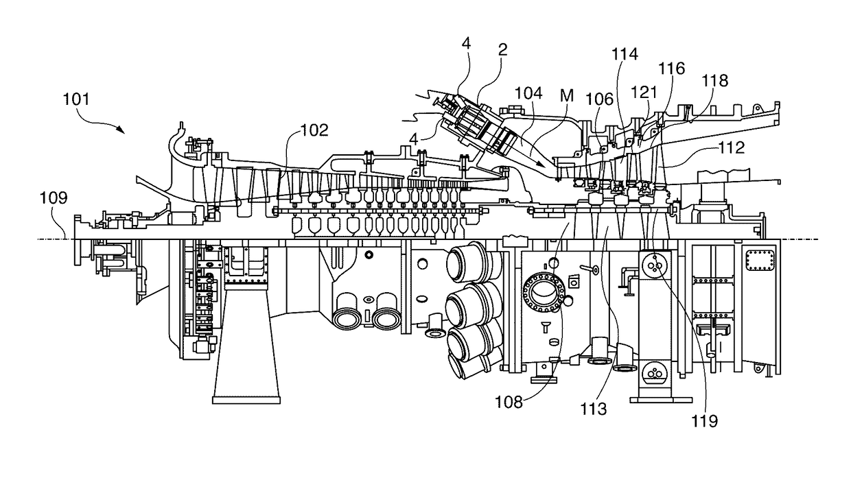
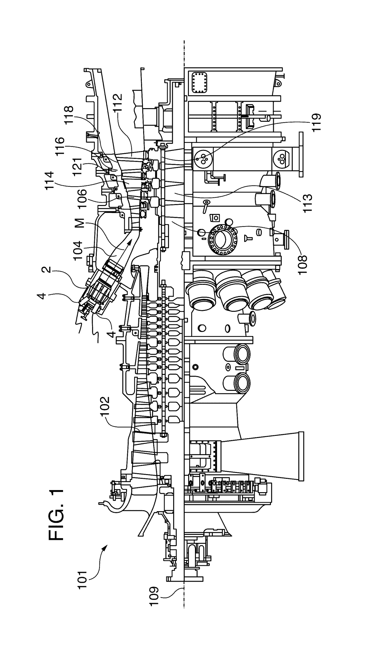
[0043]FIG. 1 shows the gas turbine 101. The lower half of FIG. 1 shows a view from above, the upper half a cross-sectional view. A gas turbine 101 is a flow machine. It has a compressor 102 for combustion air, a combustion chamber 104, as well as a turbine unit 106 for driving the compressor 102 and a generator (not shown) or a work machine. Toward that end the rotating parts of turbine unit 106 and compressor 102 are arranged on the rotor 108, to which the generator or work machine is also connected and which is rotatably mounted around its central axis 109. The combustion chamber 104 implemented in a can-annular design in the exemplary embodiment comprises a number of tube-shaped individual combustors 2 which may include baskets. Each of the combustors 2 is equipped for combusting a liquid or gaseous fuel.

[0044]The turbine unit 106 has a number of rotatable moving blades 112. The moving blades 112 are part of the rotor 108 and are arranged annularly on turbine disks 113, thus form...


PUM

PropertyMeasurementUnit
frequencyaaaaaaaaaa
timeaaaaaaaaaa
frequenciesaaaaaaaaaa

Abstract

The flame status of a group of gas turbine combustors is acoustically monitored using dynamic pressure sensors within the combustor. Dynamic pressure sensor output signals are received from the sensors and processed to determine flame status. The signals are processed both by performing a correlation analysis within each combustor and by applying a wavelet-based flame detection algorithm to each output signal. A flame is determined to be present based on the correlation analysis and the wavelet-based flame detection algorithm. The wavelet-based flame detection algorithm is chosen based on whether the gas turbine combustors are in an ignition phase or a monitoring phase.

Description

CROSS-REFERENCE TO RELATED APPLICATIONS[0001]This application incorporates by reference in its entirety as if fully set forth herein copending International Application PCT / EP2014 / 054524 entitled “Method for Monitoring a Flame State,” filed on Mar. 10, 2014, published as International Publication No. WO / 2014 / 166680 on Oct. 16, 2014.[0002]This application incorporates by reference in their entirety as if fully set forth herein the following co-pending United States utility patent application:[0003]“Single Dynamic Pressure Sensor Based Flame Monitoring of a Gas Turbine Basket” filed Oct. 14, 2014, Ser. No. 14 / 513,316;[0004]This application also incorporates by reference in its entirety as if fully set forth herein U.S. Pat. No. 7,853,433, “Combustion Anomaly Detection Via Wavelet Analysis Of Dynamic Sensor Signals”, issued Dec. 14, 2010.BACKGROUND[0005]1. Field of the Invention[0006]The invention relates to methods and apparatus for monitoring the flame state in a combustion chamber o...

Claims


Application Information

Patent Timeline
Patent Type & Authority Patents(United States)
IPC IPC(8): G01M15/14G01L19/06
CPCG01L19/0663G01M15/14
Inventor CLAUSSEN, HEIKOULERICH, NANCY H.MOMIN, ZAINULROSCA, JUSTINIAN
Owner SIEMENS ENERGY INC
Why Eureka
Try Eureka