Busbar module unit

a busbar module and module technology, applied in the field of busbar module units, can solve the problems of increased size of the busbar module, difficulty in forming the structure in one body through injection molding, wear and tear of the sheath of the voltage detection wire, etc., and achieve the effect of suppressing the complexity of the structur

Active Publication Date: 2017-03-21
YAZAKI CORP
View PDF19 Cites 2 Cited by
  • Summary
  • Abstract
  • Description
  • Claims
  • Application Information

AI Technical Summary

Benefits of technology

[0010]An object of the present disclosure is to avoid contact between a voltage detection wire and a connection terminal of a power cable while suppressing the complexity of a structure of the busbar module unit.
[0024]According to this configuration, as the connection terminal is provided in the terminal accommodating portion of the folded-back cover member, the cover member may be interposed between the connection terminal and the voltage detection wires. Therefore, the contact between the connection terminal and the voltage detection wires is avoided, thereby preventing the wear of the sheaths of the voltage detection wires. In addition, as the cover member is provided to extend in a direction in the plane of the busbar module, the complexity of the structure of the busbar module may be suppressed. Therefore, it is possible to form the cover member integrally with the busbar module through molding. Moreover, even though the surface of the folded-back cover member on the side opposing the wiring path is arranged to be pressed against the wiring path, wear of the sheaths of the voltage detection wires does not occur. Therefore, an unnecessary gap between the folded-back cover member and the busbar module may not be needed, and an increase in the size of the busbar module may be suppressed.
[0026]Accordingly, the voltage detection wires accommodated in the wiring path may be brought close to a predetermined direction, for example, the inside of the wiring path from the side edge of the wiring path by the rib. Therefore, the voltage detection wires may be prevented from being caught between the side edge of the wiring path and the cover member when the cover member is folded back.
[0028]Accordingly, when the protrusion of the cover member is inserted into the groove, the voltage detection wires positioned in the vicinity of the groove may be moved in a direction further away from the groove along the inclined surface of the protrusion, so that the voltage detection wires may be prevented from being caught on the locking protrusion.
[0029]According to the present disclosure, a contact between the voltage detection wires and the connection terminal of the power cable may be avoided while suppressing the complexity of the structure.

Problems solved by technology

In the case where the contact terminal and the voltage detection wires intersect to each other, if vibration is transmitted from the outside in a state where the voltage detection wires come in contact with the connection terminal, there is a concern that the sheath of the voltage detection wires may be worn and the conductor thereof may be exposed.
However, such structure is complex, and thus it becomes difficult to form the structure in one body through injection molding or the like.
In addition, even though such a structure is formed, there is a problem in that the size of the busbar module increases.

Method used


Image

  • Busbar module unit
  • Busbar module unit
  • Busbar module unit

Examples


Embodiment Construction

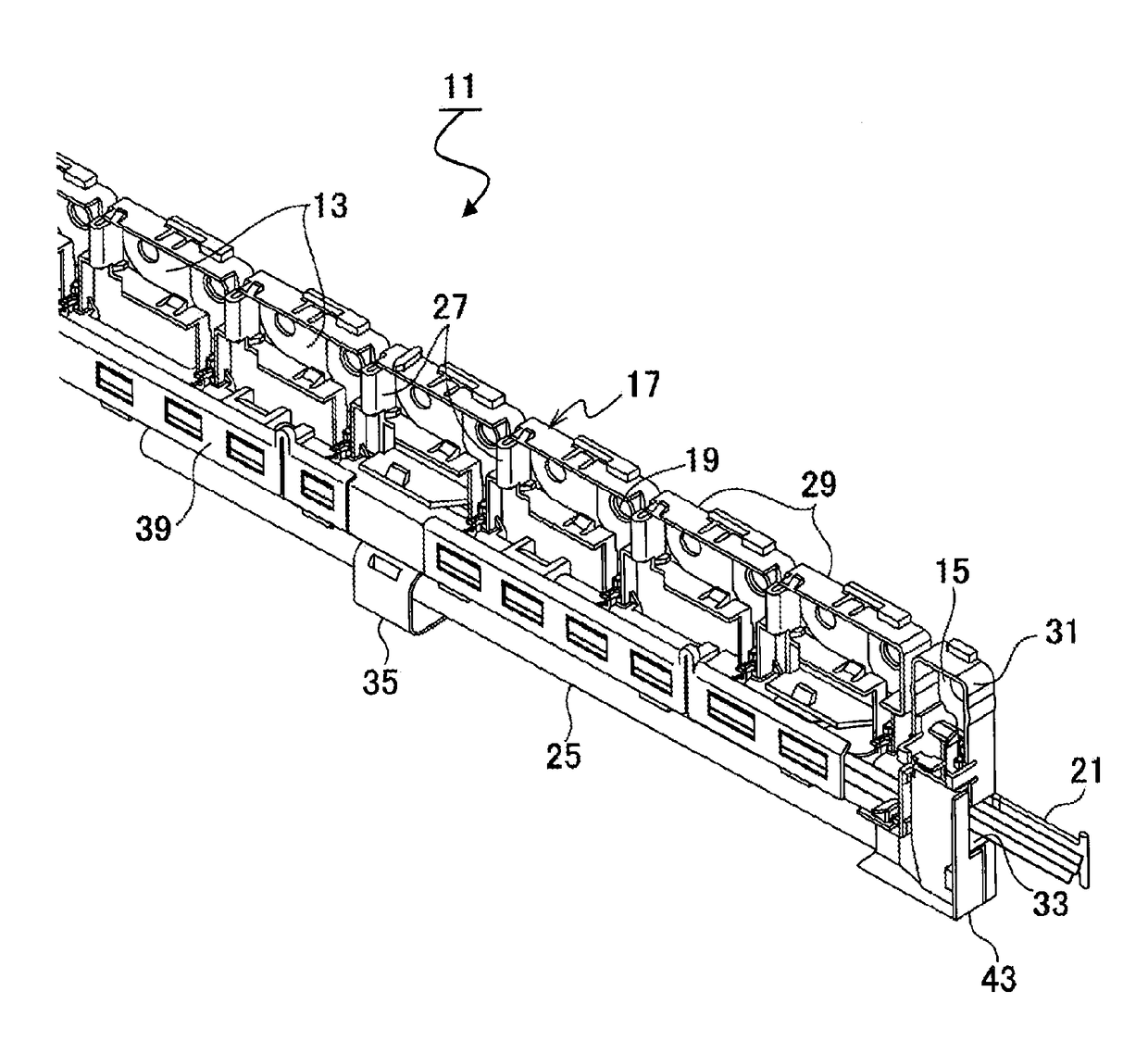
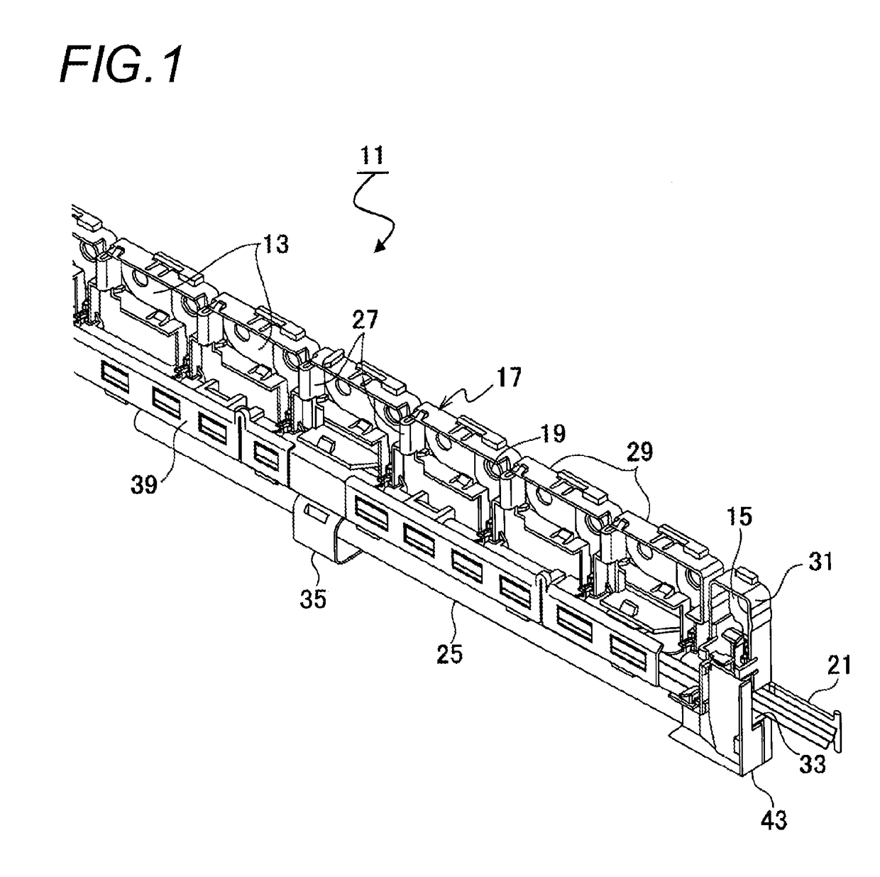
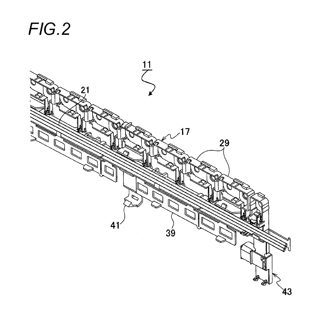
[0041]Hereinafter, an embodiment of a busbar module unit according to the present disclosure will be described with reference to the drawings.

[0042]Initially, for facilitating the description of the busbar module unit of the present disclosure, the configuration of a battery module to which the busbar module unit is mounted will be described with reference to FIG. 10.

[0043]A battery module 1 is configured to include two opposing electrode surfaces 5 of each of a plurality of batteries 3 formed as rectangular parallelepipeds so that the electrode surfaces 5 are in the same direction. A positive electrode 7 and a negative electrode 9, each of which has a cylindrical shape, protrude from the electrode surfaces of each of the batteries 3 so that the positive electrode 7 and the negative electrode 9 are alternately arranged at the adjacent batteries 3. In the battery module 1, the electrodes of the batteries 3 positioned at both ends of the plurality of batteries 3 connected in series se...


PUM

PropertyMeasurementUnit
structureaaaaaaaaaa
sizeaaaaaaaaaa
cylindrical shapeaaaaaaaaaa

Abstract

A busbar module unit includes a busbar module that is made of a resin and retains a plurality of first conductors and two second conductor, a wiring path that accommodates a plurality of voltage detection wires, a terminal accommodating portion that accommodates connection terminals of a power cable, and a cover member that is connected to the busbar module via a hinge portion. The terminal accommodating portion is integrally formed with the cover member. The wiring path is arranged so as to intersect at least one of the connection terminals. The cover member has a first face and a second face opposite to the first face, the first face opposes the wiring path when the cover member is folded back via the hinge portion. The terminal accommodating portion is formed on the second face.

Description

CROSS REFERENCE TO RELATED APPLICATIONS[0001]This application is a continuation of PCT application No. PCT / JP2012 / 066624, which was filed on Jun. 22, 2012 based on Japanese Patent Application (No. P2011-138188) filed on Jun. 22, 2011, the contents of which are incorporated herein by reference.BACKGROUND OF THE INVENTION[0002]1. Field of the Invention[0003]The present invention relates to a busbar module unit which connects a plurality of batteries in series.[0004]2. Description of the Related Art[0005]For example, in JP-A-2004-98295, a technique of using a battery module which connects a plurality of batteries in series as a power supply of an electric vehicle, a hybrid vehicle, or the like is disclosed. In the battery module, a busbar module made of a resin, which is formed by retaining a plurality of first busbars that connect the positive electrode and the negative electrode of adjacent batteries, and a second busbar which is connected to both of the total positive electrode and ...

Claims


Application Information

Patent Timeline
Patent Type & Authority Patents(United States)
IPC IPC(8): H01M2/20H01M2/10H01M10/48H01M50/209H01M50/507H01M50/51H01M50/569
CPCH01M2/206H01M2/1077H01M10/482H01M2220/20Y02E60/10H01M50/507H01M50/209H01M50/51H01M50/569
Inventor FURUYA, YOSHINOBUOGASAWARA, SHIGEYUKIINOUE, HIDEKI
Owner YAZAKI CORP
Why Eureka
Try Eureka