Female terminal

a terminal and female technology, applied in the field of female terminals, can solve the problems of difficult deformation plastically, difficult deformation of resilient pieces, unstable contact pressure with male terminals, etc., and achieve the effect of reducing contact pressure, enhancing the rigidity of the excessive deflection preventing portion, and preventing excessive deflection

Active Publication Date: 2017-03-21
SUMITOMO WIRING SYST LTD
View PDF15 Cites 3 Cited by
  • Summary
  • Abstract
  • Description
  • Claims
  • Application Information

AI Technical Summary

Benefits of technology

[0008]Excessive deflection of the resilient piece is prevented at two positions, namely, at the front and rear abutting portions of the excessive deflection preventing portion. Thus, a seated posture of the resilient piece on the excessive deflection preventing portion is stable. More particularly, if the resilient piece contacts an abutting portion at only one position, the resilient piece is deflected easily at opposite front and rear ends of this abutting portion. However, in accordance with the invention, the resilient piece contacts abutting portions at two positions, and extends along a substantially straight line connecting the abutting portions. Therefore, excessive deflection of the resilient piece is prevented at least between the abutting portions.
[0009]Further, a stress is distributed more when the resilient piece contacts the abutting portions at two positions than when it contacts the abutting portion at only one position. Thus, the resilient piece is difficult to deflect and difficult to deform plastically at each abutting portion. Furthermore, a displacement amount associated with the deflection of the resilient piece becomes smaller and a contact pressure with the male terminal becomes stable. Therefore, the performance of the resilient piece can be maintained within a range where the resilient piece is not deformed plastically.
[0012]Since the contact pressure with the male terminal is a pressure applied from the contact portion of the resilient piece to press the male terminal, a displacement of the contact portion is suppressed and the contact pressure with the male terminal becomes more stable by the contact of either one of the abutting portions with the contact portion.
[0014]According to such a configuration, the rolling of the resilient piece at the position of the contact portion (seesaw-like swinging movements of opposite lateral parts of the resilient piece when viewed in an inserting direction of the male terminal) is suppressed, wherefore the seated position of the resilient piece on the excessive deflection preventing portion becomes more stable.
[0016]The excessive deflection preventing portion may be formed by striking a part of the peripheral wall toward the resilient piece. Forming the excessive deflection preventing portion by striking enhances the rigidity of the excessive deflection preventing portion as compared with the case where the excessive deflection preventing portion is formed by cutting and bending.
[0017]Two resilient pieces may be provided to resiliently sandwich the male terminal. Thus, even if the male terminal is displaced in a deflecting direction of the resilient piece and a contact pressure from one resilient piece is reduced, a contact pressure from the other resilient piece is increased. Thus, a reduction of the contact pressure can be prevented regardless of the displacement of the male terminal.

Problems solved by technology

As a result, seated postures of the resilient pieces on the excessive deflection preventing pieces become unstable and a contact pressure with the male terminal becomes unstable.
Thus, the resilient piece is difficult to deflect and difficult to deform plastically at each abutting portion.

Method used


Image

  • Female terminal
  • Female terminal
  • Female terminal

Examples


Embodiment Construction

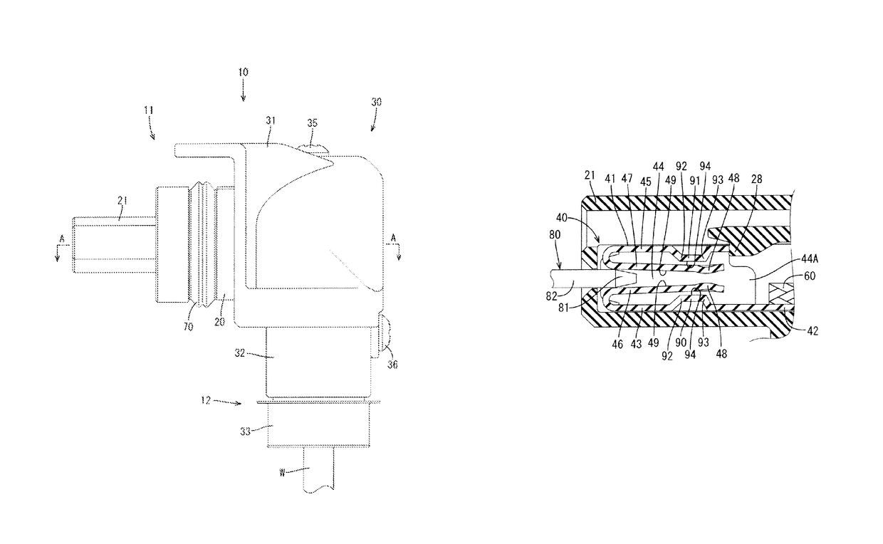
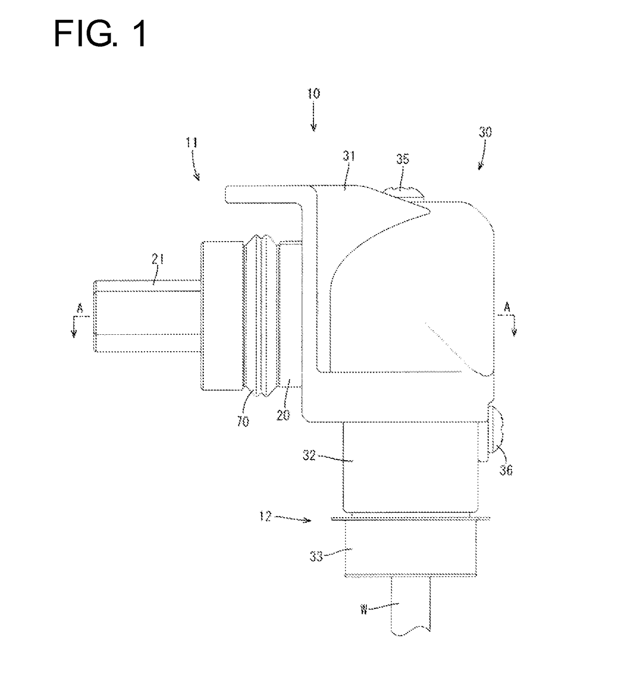
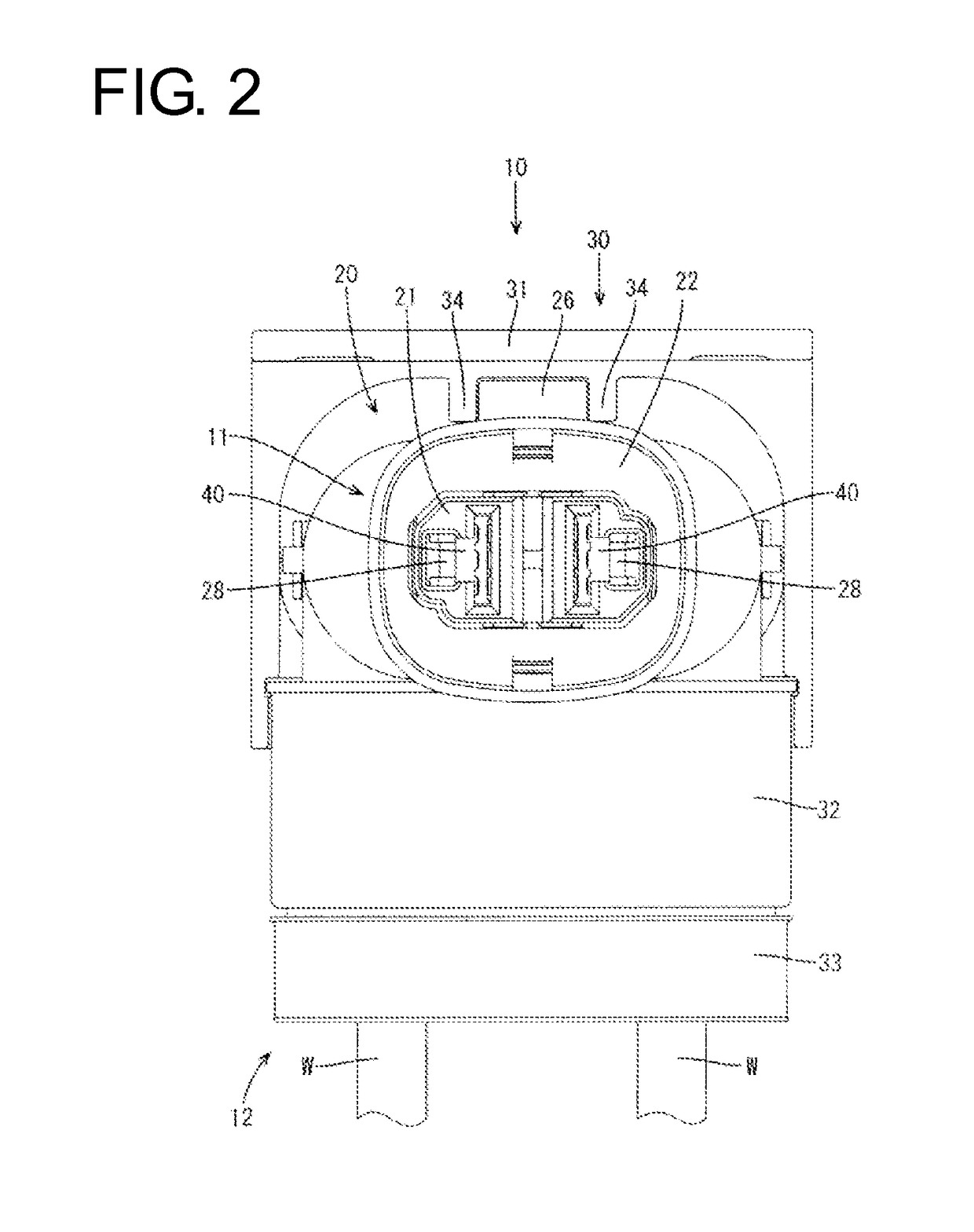
[0032]A shield connector in accordance with an embodiment is identified generally by the number 10 in FIGS. 1 to 12. The connector 10 includes a housing 20 that is substantially L-shaped in a side view. A shield shell 30 at least partly surrounds the housing 20 and wires W are drawn out from the housing 20, as shown in FIGS. 1 to 3. In the following description, a connection side with an unillustrated mating connector (left side in FIG. 1) is referred to as a front, a vertical direction is based on that of FIG. 2 and a width direction is based on a lateral direction of FIG. 2.

[0033]A connector fitting portion 11 is formed on a front end of the shield connector 10 and can fit into a mounting hole (not shown) formed on a case of a device. A wire draw-out portion 12 is formed on a lower end of the shield connector 10 and wires W are drawn out therefrom. A floating housing 21 is assembled with the connector fitting portion 11. As shown in FIG. 7, the floating housing 21 is held in a sta...


PUM


Abstract

A female terminal (40) to be connected to a male terminal (80) includes a tubular portion (41) configured by a plurality of peripheral walls. Resilient pieces (46, 47) extend in a front-back direction while facing the peripheral walls in the tubular portion (41). Excessive deflection preventing portions (90, 91) are provided on the peripheral walls, including a front abutting portion (92) and a rear abutting portion (93) arranged behind the front abutting portion (92), and configured to prevent the resilient pieces (46, 47) from being deflected excessively by contacting the resilient pieces (46, 47) at both the front and rear abutting portions (92, 93).

Description

BACKGROUND[0001]1. Field of the Invention[0002]A technology disclosed by this specification relates to a female terminal.[0003]2. Description of the Related Art[0004]U.S. Pat. No. 5,685,746 discloses a female terminal to be connected to a plate-like male terminal. This female terminal includes an electrical connecting portion that resiliently sandwiches the plate-like male terminal, a wire connecting portion to be connected to an end of a wire and a protection member for covering the electrical connecting portion. The electrical connecting portion has two pairs of resilient pieces on upper and lower side walls of a tubular base and bent to have a rectangular cross-section. The resilient piece is inclined in to a front side from the side wall and a tip part thereof is bent out into an arcuate shape.[0005]However, the above-described female terminal does not have excessive deflection preventing pieces for preventing excessive deflection of each resilient piece when a load is applied t...

Claims


Application Information

Patent Timeline
Patent Type & Authority Patents(United States)
IPC IPC(8): H01R13/11H01R13/115H01R13/52
CPCH01R13/115H01R13/113H01R13/5202
Inventor KASHIWADA, TOMOKAZUUNO, MASAFUMIITSUKI, KIYOTAKA
Owner SUMITOMO WIRING SYST LTD
Why Eureka
Try Eureka