LED light assembly

a technology of led light and assembly, which is applied in the field of optical systems, can solve the problems of compromising the pattern and intensity of light emitted, requiring frequent maintenance, and bulky prior art vehicle-mounted floodlights, and achieves the effect of less mounting depth and greater accuracy and efficiency

Active Publication Date: 2017-03-28
WHELEN ENGINEERING COMPANY
View PDF8 Cites 0 Cited by
  • Summary
  • Abstract
  • Description
  • Claims
  • Application Information

AI Technical Summary

Benefits of technology

[0011]One object of the present disclosure is to provide a compact and low profile light assembly that may be utilized in high intensity lights for mounting to motor vehicles. Supporting the optical element assembly from behind at a point eccentric to the optical axes removes the necessity for screws or standoffs resulting in an uninterrupted reflecting surface having greater accuracy and efficiency. The dimensions and relative configuration of the optical element assembly and reflector result in low profile floodlights requiring less depth for mounting and may eliminate the need for openings in body panels. Additionally, the configuration of the optical element assembly and reflector in the present disclosure does not compromise the intensity and spread of light emitted from the light assembly.

Problems solved by technology

While they emit light of sufficient intensity for the purposes of triage, prior art vehicle-mounted floodlights can be bulky, require frequent maintenance and require large amounts of electrical power.
The interruptions, which receive screws or standoffs, compromise the pattern and intensity of the light emitted.

Method used


Image

  • LED light assembly
  • LED light assembly
  • LED light assembly

Examples


Embodiment Construction

[0022]Exemplary light assemblies illustrating various aspects of the present disclosure will now be described with reference to FIGS. 1 through 7, wherein like numbers refer to like parts. Throughout the figures, it will be understood by those of skill in the art that some features and components of the warning light are omitted for clarity.

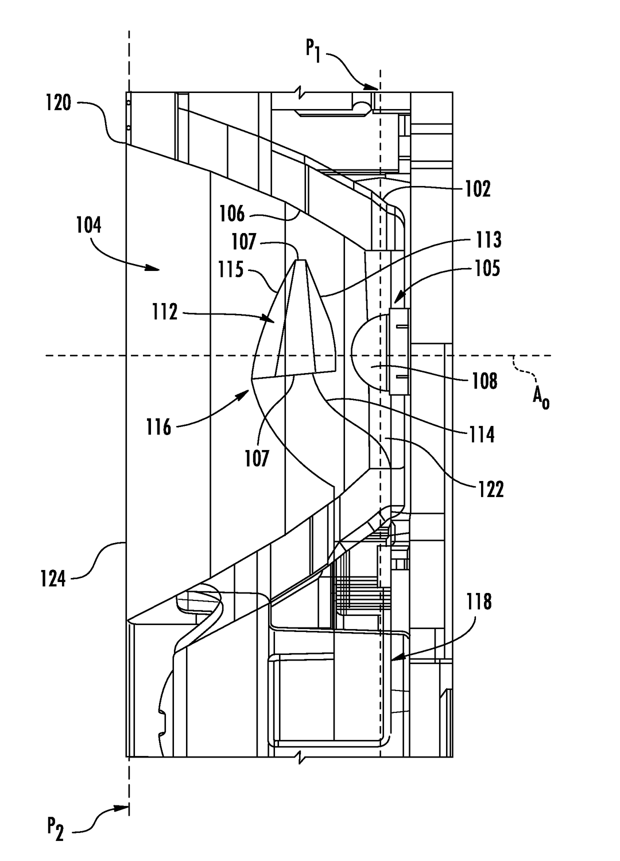
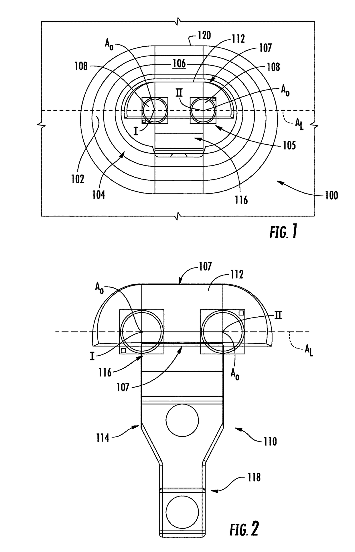
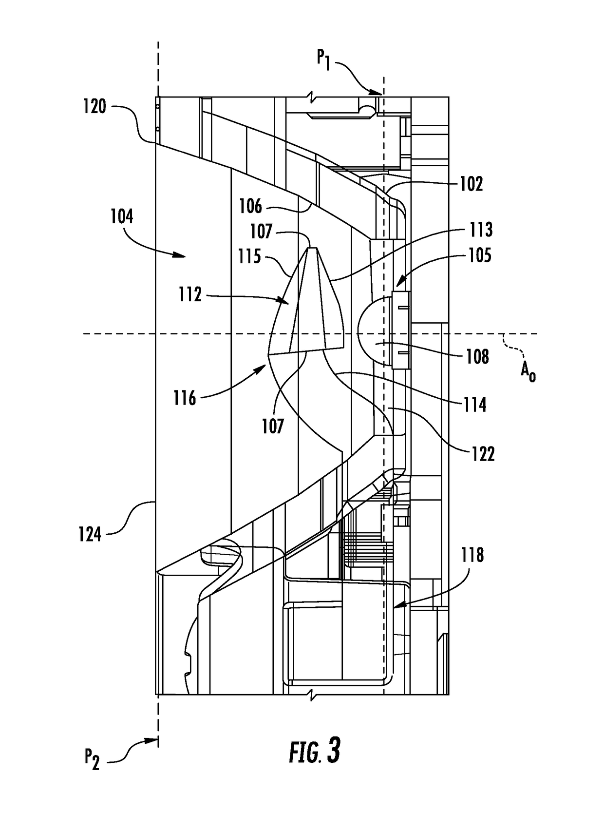
[0023]FIGS. 1-4 illustrate an embodiment of a light assembly 100 according to aspects of the disclosure. The light assembly 100 is configured for use with high intensity lights such as floodlights or area lights. As best seen in FIGS. 1 and 3, the light assembly 100 has a reflector 102 which defines an optical cavity 104. The reflector 102 reflects light emitted by an LED light source 105 incident on a reflective surface 106 along a range of reflected angles. The light source 105 comprises a light emitting die 108 having an optical axis AO perpendicular to a first plane P1 (FIG. 3A).

[0024]In the embodiment shown in FIGS. 1 and 2, the light source...


PUM


Abstract

A light assembly comprises an LED light source, a reflector, and an optical element assembly. The LED light source comprises a light emitting die and has an optical axis which extends from the light emitting die and perpendicular to a first plane. The reflector defines an optical cavity and has a reflective surface oriented to reflect light emitted by the light source incident to the reflective surface along a range of reflected angles. The optical element assembly comprises an optical element disposed in the path of the light emitted from the light source. The optical element is supported within the optical cavity by a connector arm, which has first and second ends. The first end is connected to the optical element and the second end supports the optical element assembly from behind the reflector.

Description

BACKGROUND OF THE DISCLOSURE[0001]The present disclosure relates to optical systems, and more particularly, to optical systems for use in connection with flood and area lights.[0002]Emergency first responders require adequate ground lighting to perform essential tasks such as assessing a patient's injuries and performing appropriate life-saving medical care. Consequently, floodlights having sufficient intensity to light up the area surrounding the vehicle are widely utilized on emergency vehicles. While there is no widely-accepted standard for floodlighting on emergency vehicles, standards such as the Federal KKK Standard for ambulance lighting provide guidance as to the photometric intensity and light emission pattern required for triage.[0003]When utilized in conjunction with motor vehicles, high intensity lights are traditionally mounted to the top front corners of the cab (so called “brow lights”), or mounted in an enclosure secured to a vertical side or rear face of the vehicle...

Claims


Application Information

Patent Timeline
Patent Type & Authority Patents(United States)
IPC IPC(8): F21V13/04B60Q1/32F21V13/00B60Q1/26F21Y101/00
CPCF21V13/04B60Q1/2611B60Q1/323F21Y2101/00F21Y2115/10B60Q1/247
Inventor SMITH, TODD J.
Owner WHELEN ENGINEERING COMPANY
Why Eureka
Try Eureka