Battery module having novel structure

a battery module and novel structure technology, applied in the field of battery modules with novel structures, can solve the problems of low manufacturing cost of pouch-shaped batteries, inability to arrange battery modules in longitudinal directions, and inability to increase the height of battery cell stacks, so as to achieve convenient control of battery packs

a battery module and novel structure technology, applied in the field of battery modules with novel structures, can solve the problems of low manufacturing cost of pouch-shaped batteries, inability to arrange battery modules in longitudinal directions, and inability to increase the height of battery cell stacks, so as to achieve convenient control of battery packs

US9608244B2Active Publication Date: 2017-03-28LG ENERGY SOLUTION LTD

Image

  • Battery module having novel structure
  • Battery module having novel structure
  • Battery module having novel structure

Examples


Embodiment Construction

[0053]Now, preferred embodiments of the present invention will be described in detail with reference to the accompanying drawings. It should be noted, however, that the scope of the present invention is not limited by the illustrated embodiments.

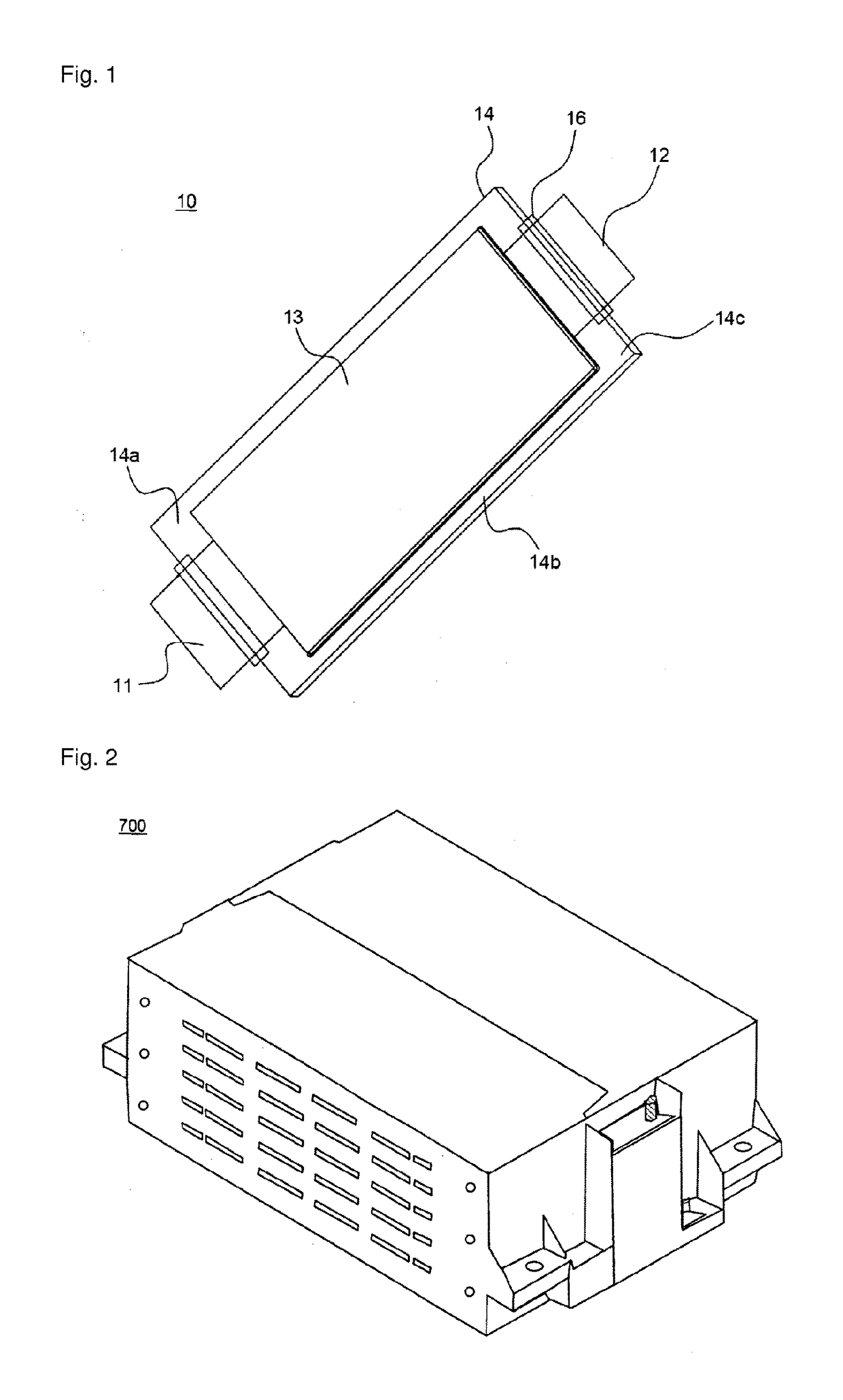
[0054]FIG. 1 is a perspective view typically illustrating an exemplary plate-shaped battery cell, which will be mounted in a battery module according to the present invention.

[0055]Referring to FIG. 1, a plate-shaped battery cell 10 is configured to have a structure in which two electrode leads 11 and 12 protrude from the upper end and the lower end of a battery body 13, respectively, so that the electrode leads 11 and 12 are opposite to each other. A sheathing member 14 includes upper and lower sheathing parts. That is, the sheathing member 14 is a two-unit member. An electrode assembly (not shown) is mounted in a receiving part which is defined between the upper and lower sheathing parts of the sheathing member 14. Opposite sides 14b, an u...


PUM

PropertyMeasurementUnit
strengthaaaaaaaaaa
lengthaaaaaaaaaa
sizeaaaaaaaaaa

Abstract

Disclosed herein is a battery module including (a) a battery cell stack including two or more battery cells or unit modules electrically connected to each other in a state in which the battery cells or unit modules are vertically stacked, (b) a first housing to cover the entirety of the end of one side of the battery cell stack and portions of the top and bottom of the battery cell stack and (c) a second housing to cover the entirety of the end of the other side of the battery cell stack and the remainder of the top and bottom of the battery cell stack, wherein the first housing and the second housing are provided with coupling holes formed to couple the first housing and the second housing to each other, the coupling holes being horizontal coupling holes, through which coupling members can be inserted in the lateral direction.

Description

CROSS REFERENCE TO RELATED APPLICATIONS[0001]This application is a Continuation of PCT International Application No. PCT / KR2011 / 004033 filed on Jun. 2, 2011, which claims priority under 35 U.S.C. ยง119(a) to Patent Application No. 10-2010-0052122 filed in the Republic of Korea on Jun. 3, 2010, all of which are hereby expressly incorporated by reference into the present application.TECHNICAL FIELD[0002]The present invention relates to a battery module having a novel structure, and, more particularly, to a battery module including (a) a battery cell stack including two or more battery cells or unit modules electrically connected to each other in a state in which the battery cells or unit modules are vertically stacked, (b) a first housing to cover the entirety of the end of one side of the battery cell stack and portions of the top and bottom of the battery cell stack and (c) a second housing to cover the entirety of the end of the other side of the battery cell stack and the remainder...

Claims


Application Information

Patent Timeline
28 Mar 2017
Publication
US9608244B2
IPC
H01M2/10; H01M10/48; H01M2/20; H01M10/656; H01M10/613; H01M10/625; H01M2/02; H01M10/647; H01M50/105; H01M50/211; H01M50/507; H01M50/51
CPC
H01M2/1077; H01M2/206; H01M2/0207; H01M10/482; H01M10/486; H01M10/613; H01M10/625; H01M10/647
Inventors
SHIN, YONG SHIK; YOON, JONG MOON