
Board stacking apparatus

a technology of stacking apparatus and stacking board, which is applied in the direction of stacking articles, conveyors, transportation and packaging, etc., can solve the problems of increasing the complexity, space, cost, and the overall complexity of the apparatus, so as to reduce the power required for such a task, increase the stacking speed of board layers, and maximize the use of space

Active Publication Date: 2016-03-01
9374-4399 QUEBEC INC
View PDF27 Cites 2 Cited by
  • Summary
  • Abstract
  • Description
  • Claims
  • Application Information

AI Technical Summary

Benefits of technology

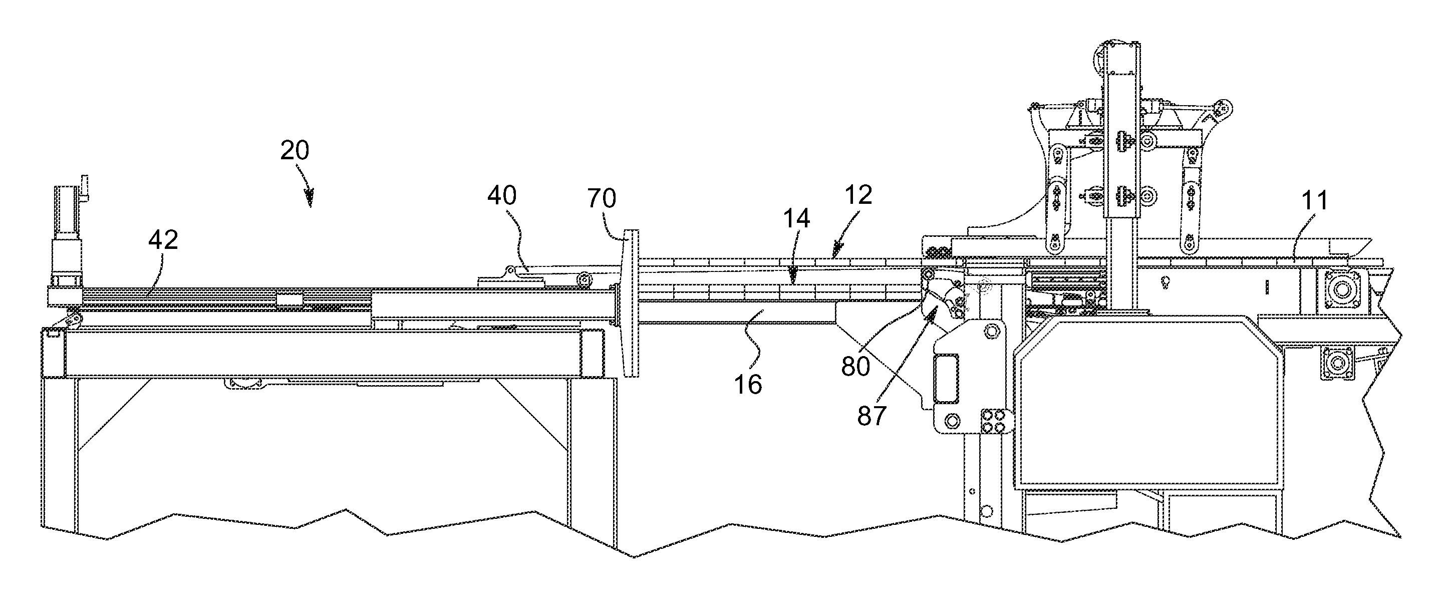
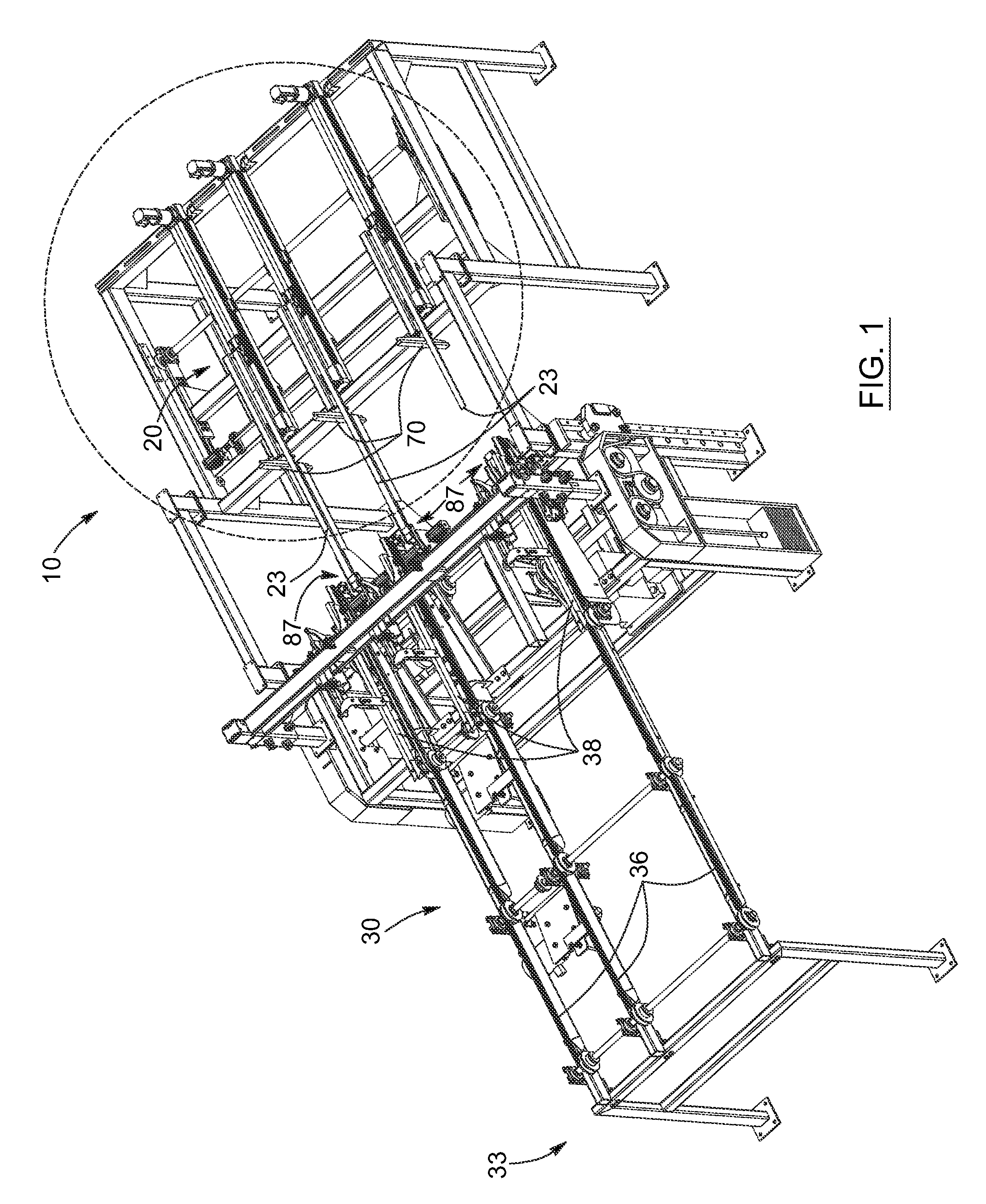
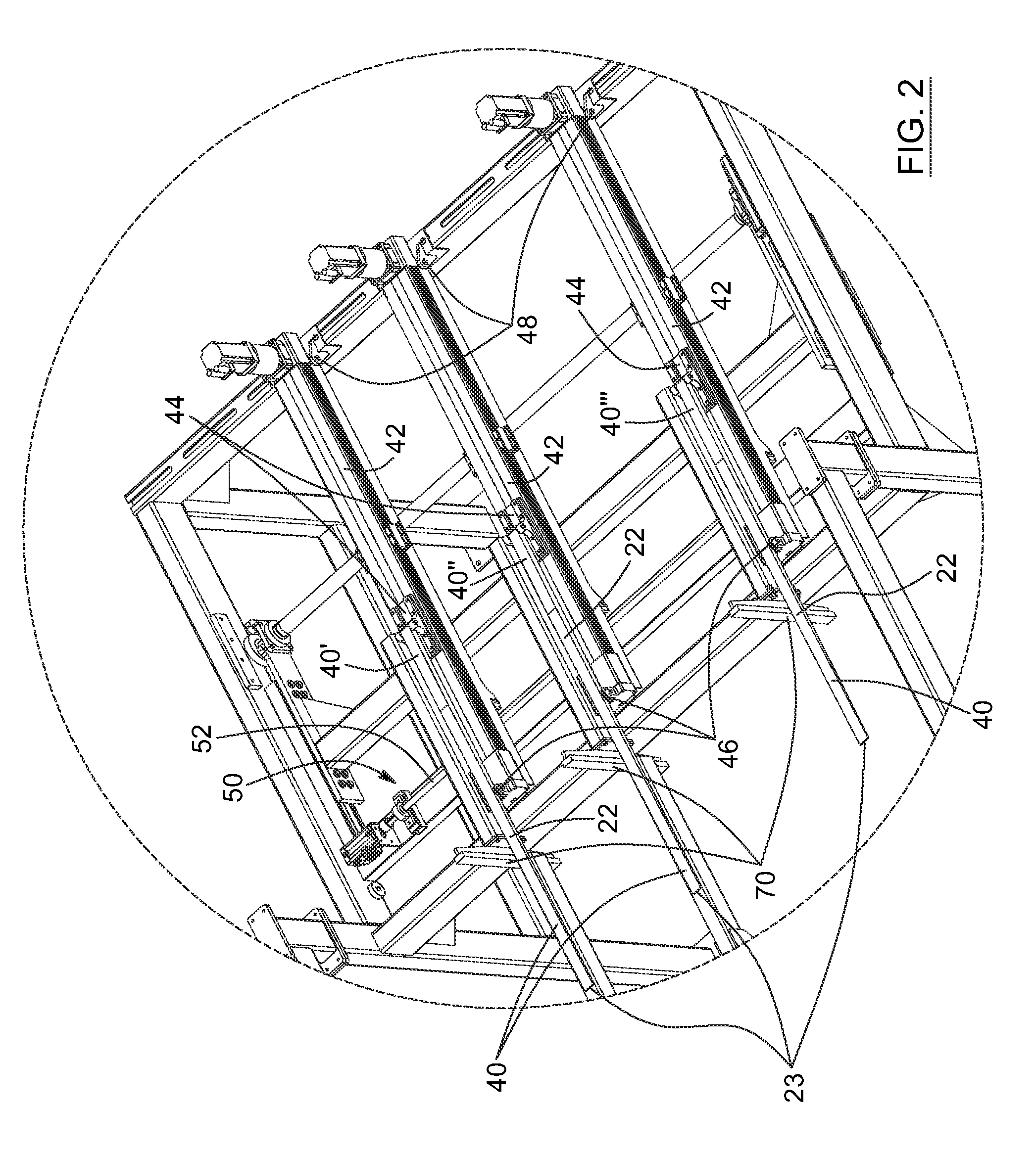
[0034]Advantageously, board stacking apparatuses according to embodiments of the present invention allow an increase in the stacking speed of board layers, as it requires a minimal displacement of the movable support or supports, which also contributes to a reduction in the power required for such a task. Also advantageously, the board stacking apparatus is preferably compact and can therefore be installed in more confined spaces than traditional board stacking apparatuses. Given the fact that lumber mills are usually crammed places where the use of space needs to be maximized, compactness is often desirable. Furthermore, stacking apparatuses according to embodiments of the invention may be designed so that none of its components interferes with the stick placing apparatus, which, when provided, is usually located above the stack holder. Both apparatuses can therefore be easily combined.

Problems solved by technology

Nowadays, in many lumber mills, this bottleneck occurs at the stacking stage, the stacking of the boards being the most time consuming operation.
Consequently, the speed of the overall process of stacking the boards is limited to the maximum pace of the arms or forks.
This pace can be improved by providing multiple sets of arms or forks operating in an alternating manner, but such a set up also increases the number of mechanical components involved, and the overall complexity, space, and cost of the apparatus.
As mentioned above, the maximum pace that can be reached by such apparatuses usually cannot cope with the pace of the other operations on the lumber mills chain of operations, all of which resulting in a bottleneck at this stage.
Moreover, this process is power consuming as the mechanism constantly has to fight inertia in the course of its movements.

Method used


Image

  • Board stacking apparatus
  • Board stacking apparatus
  • Board stacking apparatus

Examples


Embodiment Construction

[0055]In the following description, the same numerical references refer to similar elements. The embodiments, geometrical configurations, materials mentioned and / or dimensions shown in the figures or described in the present description are preferred embodiments only, given solely for exemplification purposes.

[0056]Moreover, although the preferred embodiment of the board stacking apparatus and corresponding parts thereof consists of certain geometrical configurations as explained and illustrated herein, not all of these components and geometries are essential to the invention and thus should not be taken in their restrictive sense, i.e. should not be taken as to limit the scope of the present invention. It is to be understood, as also apparent to a person skilled in the art, that other suitable components and cooperation thereinbetween, as well as other suitable geometrical configurations, may be used for the board stacking apparatus according to the present invention, as will be br...


PUM


Abstract

A board stacking apparatus having one or more movable supports having at least two arms each, a rear stopper and a power assembly operatively connected to the movable support to move the same according to a layer stacking routine. The layer stacking routine includes positioning the movable support at a receiving position, maintaining the movable support in the receiving position while the boards are dispensed thereon, and moving the movable support in a rearward direction. The board stacking apparatus further comprises abutment components located proximate to and slightly below a board dispensing mechanism of the apparatus to support the receiving end of corresponding arms when in the receiving position.

Description

RELATED APPLICATION[0001]This is a continuation-in-part of PCT patent application PCT / CA2011 / 001388, filed Dec. 20, 2011, which claims priority of U.S. Provisional patent application No. 61 / 425,151, filed Dec. 20, 2010, which applications are incorporated herein by reference. To the extent appropriate, a claim of priority is made to each of the above disclosed applications.FIELD OF THE INVENTION[0002]The present invention relates to automated wood processing equipment and more particularly concerns a board stacking apparatus having an improved design.BACKGROUND OF THE INVENTION[0003]Over time, the mechanization of the processes in lumber mills has permitted an increase in the speed of the associated operations such as, but not limited to, sawing, edging, trimming, planning, stacking and bundling. However, as it is the case for every process including multiple operations, for the overall process to be effective, lumber need to flow smoothly between successive operations. If one of th...

Claims


Application Information

Patent Timeline
Patent Type & Authority Patents(United States)
IPC IPC(8): B65G57/22B65G57/24
CPCB65G57/24B65G57/245B65G2201/0282
Inventor ST-PIERRE, MICHELST-PIERRE, ISABELLEVALLEE, ERIC
Owner 9374-4399 QUEBEC INC
Learn More