Vertically die-stacked bonder and method using the same

a bonder and die-stacked technology, applied in the direction of semiconductor/solid-state device details, electrical apparatus, semiconductor devices, etc., can solve the problems of poor bonding rate between semiconductors, high production cost, low production speed, etc., and achieve the effect of reducing production cost, increasing the maximum number of stackable die layers, and enhancing production speed

Active Publication Date: 2019-10-08
GALLANT MICRO MACHINING
View PDF1 Cites 0 Cited by
  • Summary
  • Abstract
  • Description
  • Claims
  • Application Information

AI Technical Summary

Benefits of technology

[0008]Accordingly, it is an object of the present invention to provide a vertically die-stacked bonder and a method using the vertically die-stacked bonder that can produce a vertical state of dies by elevating each of the dies by 90 degrees and then stack the dies orderly and laterally, such that the production speed can be enhanced, the production cost can be reduced, the maximum number of stack-able die layers can be increased, and the binding of the dies can be strengthened.
[0023]As stated above, the vertically die-stacked bonder and the method using the same of the present invention are to elevate the die by 90 degrees so as to set the die in the vertical state, and then to stack laterally the dies in the vertical state orderly, such that the stacking speed of the dies can be increased, the production cost can be reduced, and the productivity can be enhanced. Also, the number of die-stacked layers can be increased.

Problems solved by technology

One of these shortcomings is the low production speed, another thereof is the high production cost, and the third thereof is the poor binding rate between semiconductors.
Thereby, the number of stacking layers would be limited.

Method used


Image

  • Vertically die-stacked bonder and method using the same
  • Vertically die-stacked bonder and method using the same
  • Vertically die-stacked bonder and method using the same

Examples


first embodiment

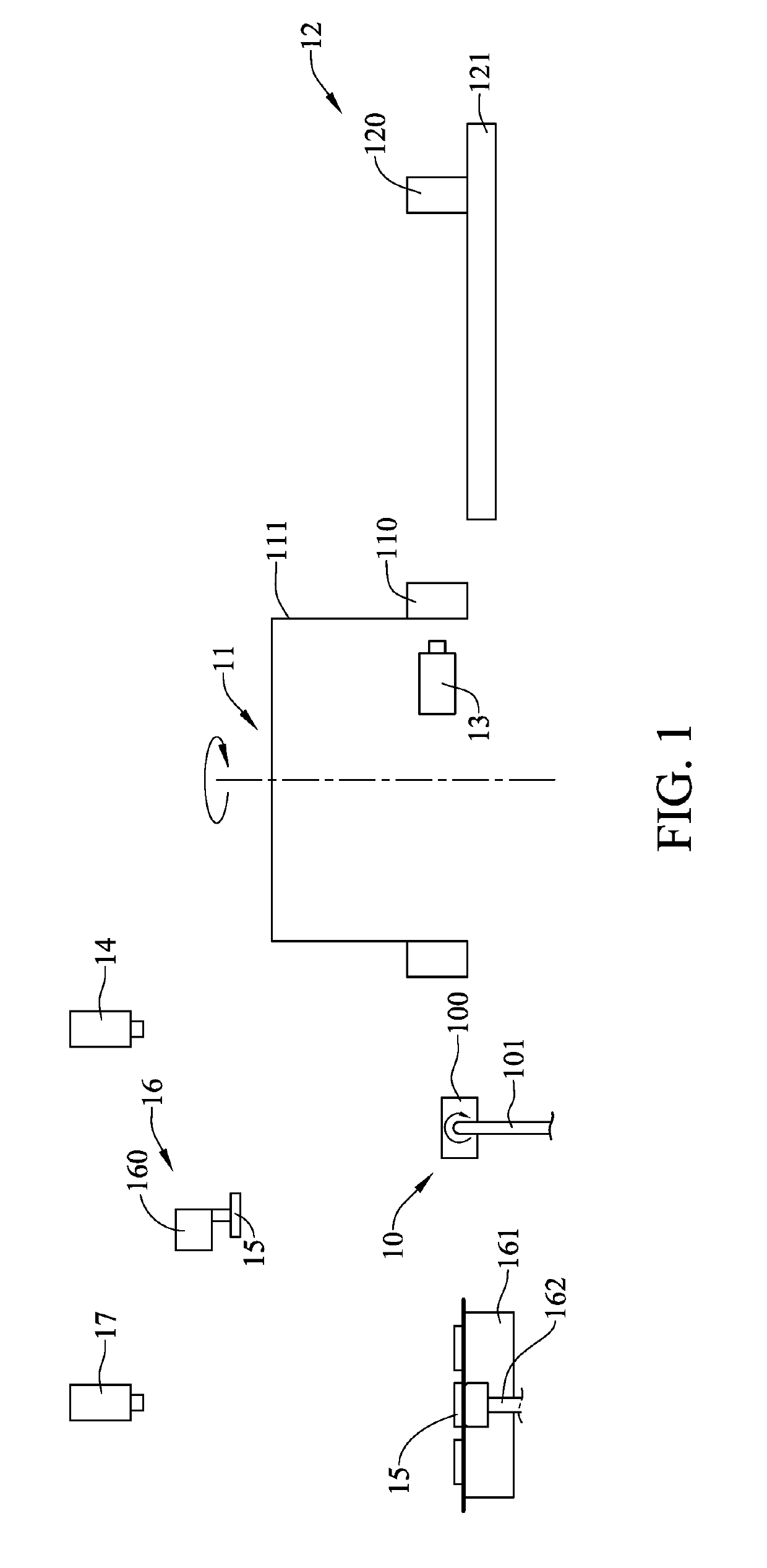
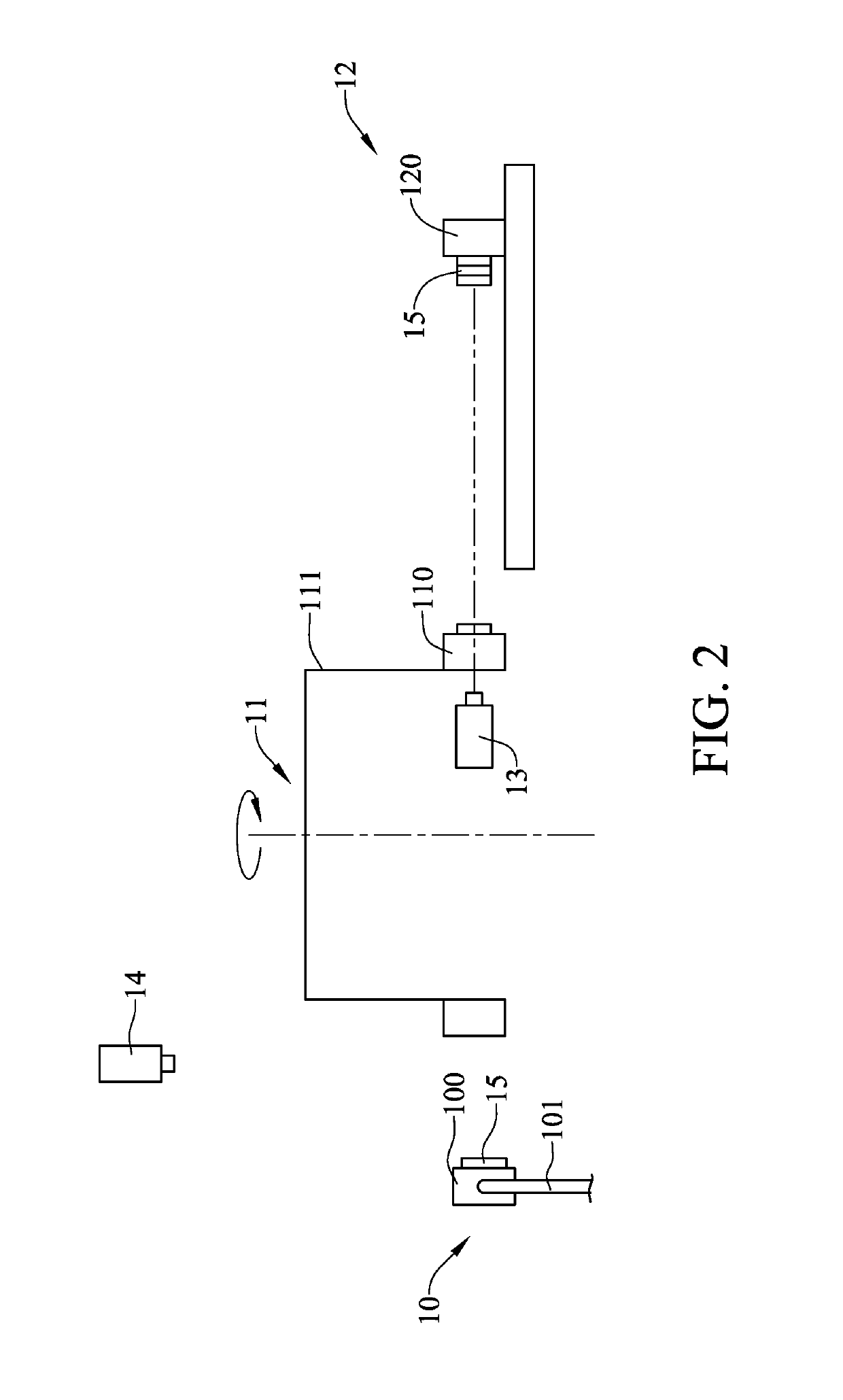
[0031]Referring now to FIG. 1, a schematic view of the vertically die-stacked bonder in accordance with the present invention is shown. The vertically die-stacked bonder includes a self-elevating unit 10, a retrieval unit 11, a receiving unit 12, a first vision unit 13, a second vision unit 14, a supply unit 16 and a third vision unit 17.

[0032]The self-elevating unit 10 has a self-elevating carrier 100 and a self-elevating displacement module 101, in which the self-elevating displacement module 101 is coupled with the self-elevating carrier 100.

[0033]The retrieval unit 11 neighbored to the self-elevating unit 10 has at least two sucking modules 110 and a rotational retrieval module 111, in which the sucking modules 110 are individually mounted to the rotational retrieval module 111.

[0034]The receiving unit 12 neighbors to the retrieval unit 11 has a receiving carrier 120 and a receiving displacement module 121, in which the receiving carrier 120 is located on the receiving displacem...

second embodiment

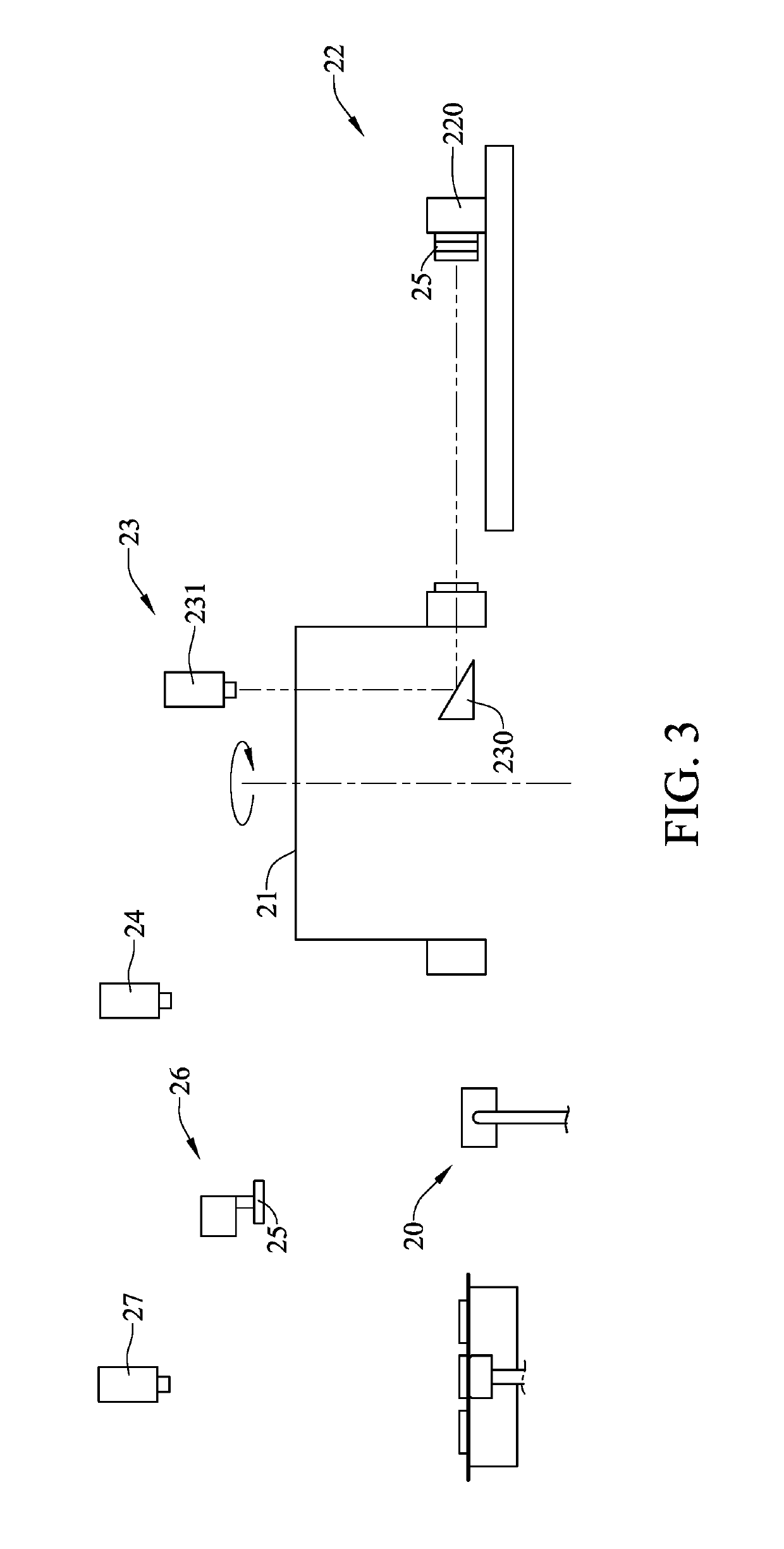
[0039]Referring now to FIG. 3, a schematic view of the vertically die-stacked bonder in accordance with the present invention is shown. The vertically die-stacked bonder includes a self-elevating unit 20, a retrieval unit 21, a receiving unit 22, a first vision unit 23, a second vision unit 24, a supply unit 26 and a third vision unit 27.

[0040]In this second embodiment, the self-elevating unit 20, the retrieval unit 21, the receiving unit 22, the second vision unit 24, the supply unit 26 and the third vision unit 27 are the same to those in the first embodiment, and thus details thereabout are omitted herein.

[0041]The first vision unit 23 has a lens module 230 and an image-capturing module 231, in which the lens module 230 is located under the retrieval unit 21 at a position facing the receiving carrier 220, and the image-capturing module 231 is located above the retrieval unit 21 at a place opposing to the lens module 230 with respect to the retrieval unit 21.

[0042]Referring now to...


PUM


Abstract

A vertically die-stacked bonder able to stack laterally dies one by one includes a self-elevating unit, a retrieval unit neighbored to the self-elevating unit, and a receiving unit neighbored to the retrieval unit. At least one die is located at the self-elevating unit. The self-elevating unit elevates one die by 90 degrees, so as to form a vertical state. The retrieval unit hands over the die in the vertical state to the receiving unit. The self-elevating unit then elevates another die by 90 degrees once again. The retrieval unit stacks laterally the another die in the vertical state to the previous die at the receiving unit. Thereupon, by stacking laterally the dies in the vertical state orderly, the speed of die stacking can be increased, the production costs can be reduced, and the productivity can be increased.

Description

[0001]This application claims the benefit of Taiwan Patent Application Serial No. 106114523, filed May 2, 2017, the subject matter of which is incorporated herein by reference.BACKGROUND OF THE INVENTION[0002](1) Field of the Invention[0003]The invention relates to a vertically die-stacked bonder and a method using the same, and more particularly to the vertically die-stacked bonder and the method using the vertically die-stacked bonder that can elevate the die elevate by 90 degrees so as to achieve a vertical state of die, such that a plurality of dies can be orderly and laterally stacked together. Thereupon, the stacking efficiency of the dies can be enhanced, the production speed can be increased, and the production cost can be reduced.[0004](2) Description of the Prior Art[0005]Recently, one of mainstream technology in the semiconductor industry is to chase multi-functions, high-capacity, compactness and minimization. For example, the stacked package on package (PoP) is a techno...

Claims


Application Information

Patent Timeline
Patent Type & Authority Patents(United States)
IPC IPC(8): H01L23/00
CPCH01L24/75H01L24/80H01L24/94H01L24/741H01L2224/75753H01L2224/75822H01L2224/75745H01L2224/75824H01L21/67121H01L21/67718H01L21/6838
Inventor SHIH, TUN-CHIHHUANG, LIANG-YIN
Owner GALLANT MICRO MACHINING
Why Eureka
Try Eureka