Narrow-angle directional microphone

a directional microphone and narrow-angle technology, applied in the direction of transducer details, electrical transducers, electrical apparatus, etc., can solve the problems of noise and easy damage of narrow-angle directional microphones, and achieve the effect of easy replacement of acoustic tubes

Inactive Publication Date: 2017-03-28
AUDIO-TECHNICA
View PDF2 Cites 2 Cited by
  • Summary
  • Abstract
  • Description
  • Claims
  • Application Information

AI Technical Summary

Benefits of technology

[0024]The present invention has been made in view of the above-described problem in the conventional narrow-angle directional microphone to which the acoustic tube is attached with the fixing screws, and an objective is to provide a narrow-angle directional microphone that is less likely to be damaged even if bending stress is applied to the microphone, and enables easy attachment / detachment of the acoustic tube.
[0036]Further, the acoustic tube can be detached by cancelling the tightening of the bolts. Therefore, replacement work of the acoustic tube is easy. Further, the acoustic tube is held by elastic deformation of the first elastic member. Therefore, unique function and effect to be less likely to be damaged even if bending stress is applied to the microphone can be obtained.

Problems solved by technology

Therefore, the narrow-angle directional microphone has a problem of being easily damaged when stress is applied to the relay member 12 that is a joint portion of the acoustic tube.
The looseness of the fixing screw 23 caused as described above becomes a cause of occurrence of noises during the use of the microphone.

Method used


Image

  • Narrow-angle directional microphone
  • Narrow-angle directional microphone
  • Narrow-angle directional microphone

Examples


Embodiment Construction

[0048]A narrow-angle directional microphone according to the present invention will be described based on embodiments illustrated in the drawings. Note that a configuration of a microphone unit included in the narrow-angle directional microphone described below is the same as the configuration of the microphone unit 1 described based on FIGS. 4A and 4B. Therefore, in the drawings described below, the entire microphone unit is denoted with the reference sign 1, and description of the reference signs of respective units of the microphone unit and detailed description thereof are omitted.

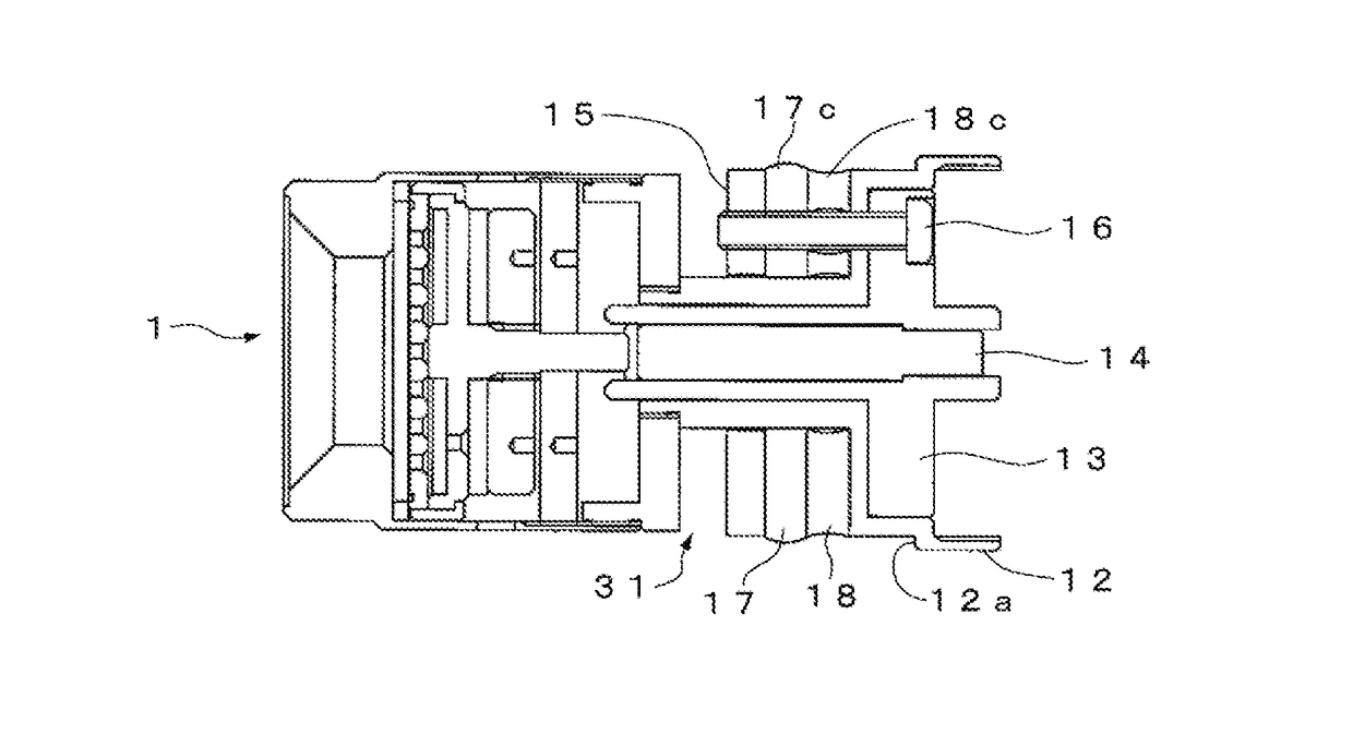
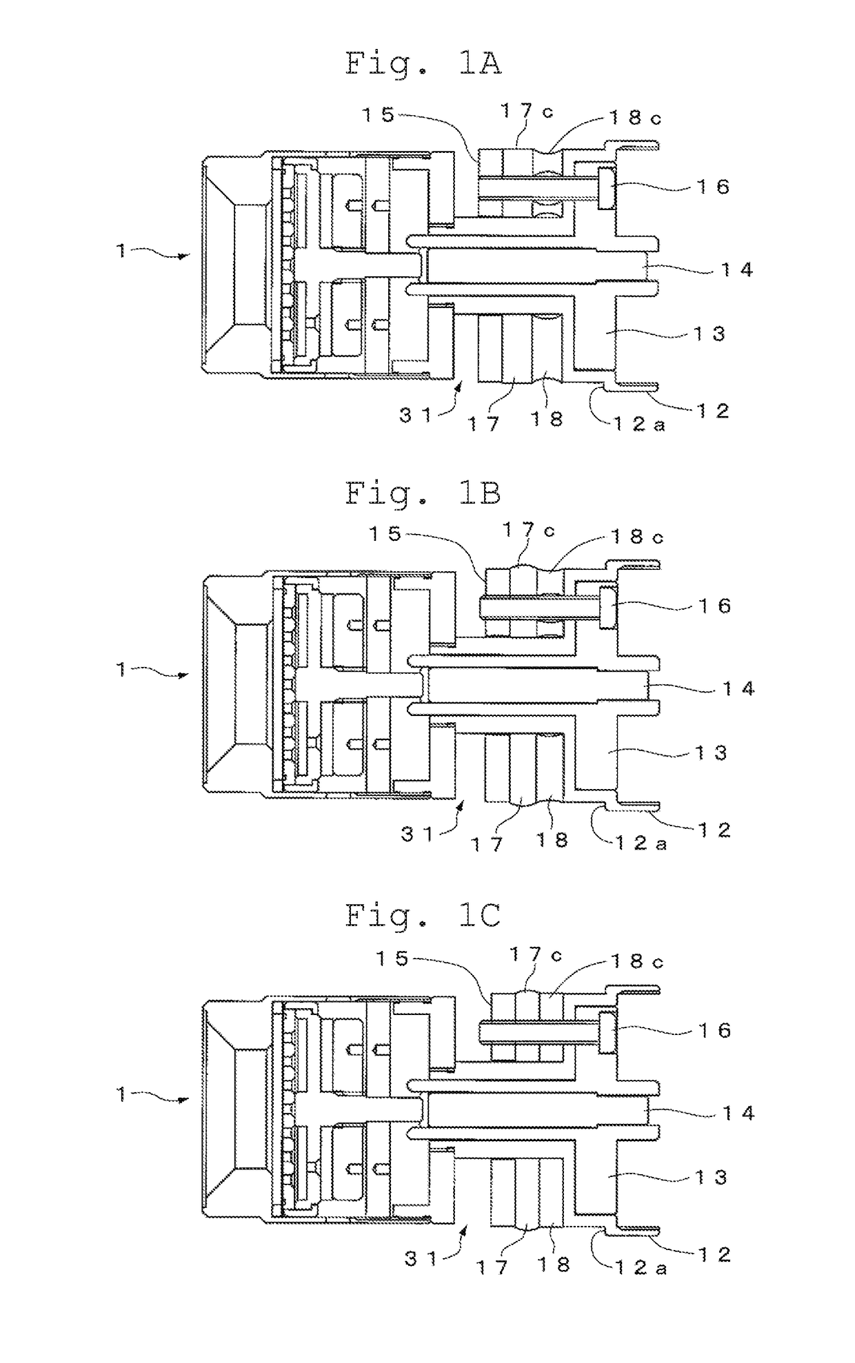
[0049]FIGS. 1A to 1C are sectional views illustrating a configuration of an acoustic tube attaching unit 31 arranged on a back surface side of the microphone unit 1. In the acoustic tube attaching unit 31, a relay member 12, an insulating base 13, and a drawing rod 14 described based on FIGS. 4A and 4B are used as a part of configuration elements. Then, similarly to the example illustrated in FIGS. 4A ...


PUM


Abstract

An acoustic tube attaching unit that attaches an acoustic tube to a side of a main body case where a microphone unit is mounted. The acoustic tube attaching unit includes first and second elastic members lying between a fixing member and a washer, and bolts that tight the fixing member and the washer in an axial direction. A peripheral edge surface of the first elastic member is formed in a linear manner, and a peripheral edge surface of the second elastic member is formed in a recessed surface manner, so that the peripheral edge surface of the first elastic member protrudes in an outer peripheral direction by elastic deformation by the tightening of the bolts. The acoustic tube is attached to the main body case side by fixing action to an inner wall of the acoustic tube by the protrusion of the first elastic member in the outer peripheral direction.

Description

RELATED APPLICATIONS[0001]The present application is based on, and claims priority from, Japanese Application No. JP2015-028654 filed Feb. 17, 2015 , the disclosure of which is hereby incorporated by reference herein in its entirety.BACKGROUND OF THE INVENTION[0002]Field of the Invention[0003]The present invention relates to a narrow-angle directional microphone that allows an acoustic tube to be atachably / detachably mounted to a main body case that includes a microphone unit, and especially relates to a narrow-angle directional microphone with a devised attaching structure of the acoustic tube to the main body case.[0004]Description of the Related Art[0005]As a narrow-angle directional microphone, one using a long and narrow acoustic tube, and having a microphone unit arranged near a rear end portion of the acoustic tube in a length direction is known. This narrow-angle directional microphone has a characteristic to detect only a sound wave entering from a direction of a front end ...

Claims


Application Information

Patent Timeline
Patent Type & Authority Patents(United States)
IPC IPC(8): H04R9/08H04R1/34
CPCH04R1/342
Inventor AKINO, HIROSHI
Owner AUDIO-TECHNICA
Why Eureka
Try Eureka