Scanning of a human body part with high-energy radiation emitted by the body part

a body part and radiation technology, applied in the direction of instruments, diaphragms for radiation diagnostics, patient positioning for diagnostics, etc., can solve the problem that the screening of that other body part by a wall or table with lead or the like is only partially effective in a scanner, so as to achieve the effect of reducing radiation load, saving costs, and keeping sensitivity high

Active Publication Date: 2017-04-04
MILABS BV
View PDF11 Cites 2 Cited by
  • Summary
  • Abstract
  • Description
  • Claims
  • Application Information

AI Technical Summary

Benefits of technology

[0006]An object of the present invention is to provide a scanner which at least partially counters this drawback, or at least constitutes a useful alternative for existing scanners. In addition, an object is to enable more efficient use of the detector surface, and thus make cost savings possible. It is also an object both to keep the sensitivity high, since that allows a lower radiation load for the person to be examined, and to have a high resolution, since that allows a better image and thus better diagnosis.SUMMARY OF THE INVENTION

Problems solved by technology

A screening of that other body part by a wall or table with lead or the like is only partially effective in a scanner.

Method used


Image

  • Scanning of a human body part with high-energy radiation emitted by the body part
  • Scanning of a human body part with high-energy radiation emitted by the body part
  • Scanning of a human body part with high-energy radiation emitted by the body part

Examples


Embodiment Construction

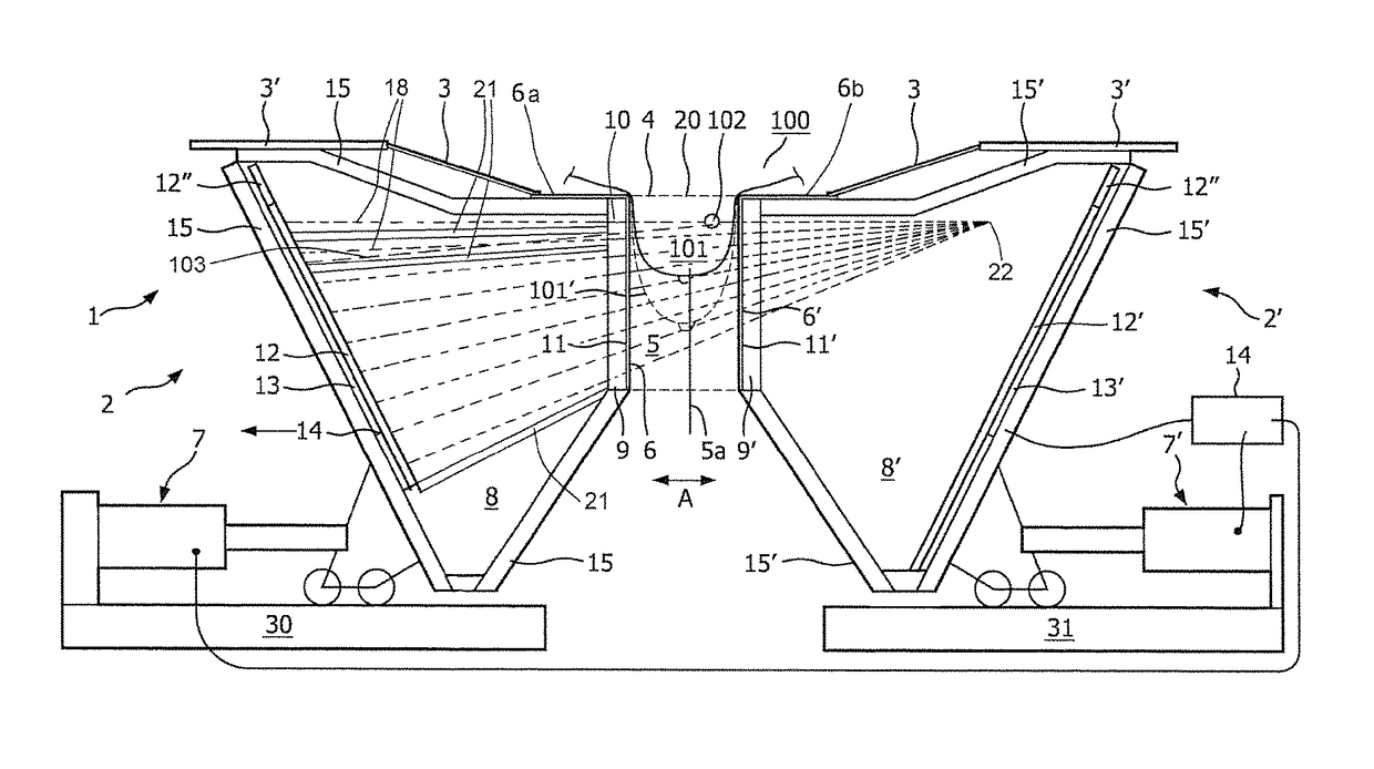
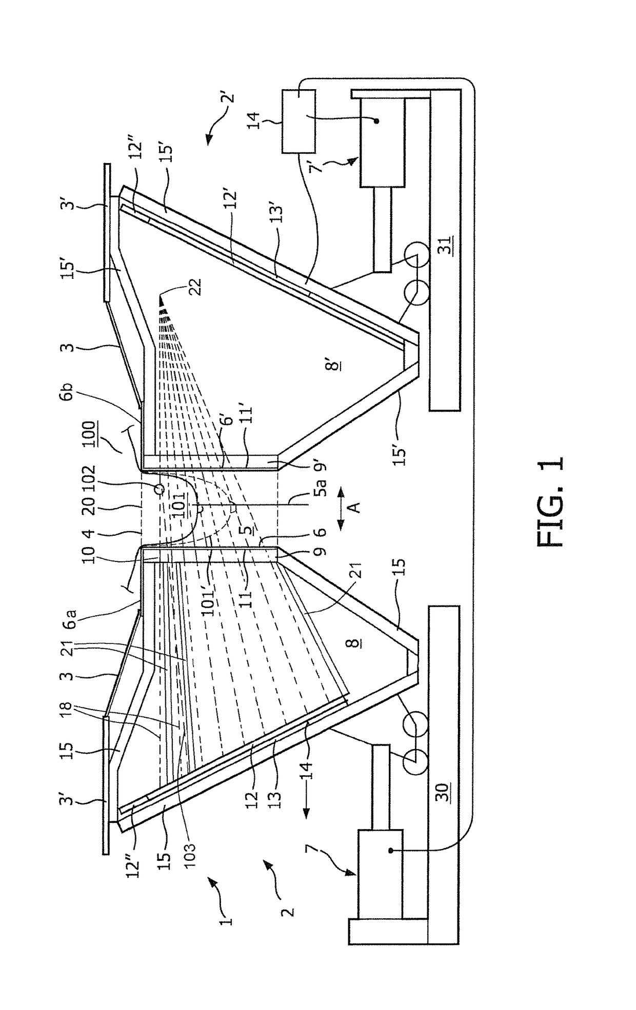
[0067]FIG. 1 shows schematically an example of a scanner 1 according to the invention, in side view in cross section.

[0068]The shown scanner 1 has two cameras, denoted in general terms by 2 and 2′, as well as a supporting part 3 for supporting the upper body 100 of a woman, and compression components 6, 6′.

[0069]In this example, the supporting part 3 is realized as a table, at least for laying of the upper body 100 thereon. In another embodiment, the table 3 is arranged to lay the whole person thereon. In yet another embodiment, the upper body 100 of the person is not horizontal but upright, for example in the case of a person whose breast or other body part is portrayed by the scanner 1 in a sitting or standing attitude. In these latter variants, the part 3 shall stand upright, or, for example, at an oblique angle.

[0070]The supporting part 3 has an introduction opening 4 having behind it, i.e., during use of the shown scanner 1, below it, a receiving space or cavity 5 for receiving...


PUM


Abstract

A scanner for scanning a body part of a human, such as, for example, a breast of a woman includes a supporting part for the upper body of a human, a receiving space for the body part to be scanned, possibly a compression device for pressing against the body part introduced into the receiving space, and a camera which is arranged to form an image of the body part introduced into the receiving space and pressed against by the compression device, with the aid of high-energy radiation emitted by the body part. The camera includes a collimator having a movable collimator part which has an incident surface facing towards the receiving space. The collimator defines and delimits an astigmatic, two-dimensional collection of radiation channels for the high-energy radiation.

Description

CROSS-REFERENCE TO RELATED APPLICATIONS[0001]This application is the National Stage of International Application No. PCT / NL2015 / 050212 filed Apr. 2, 2015, which claims the benefit of Netherlands Application No. NL 2012546, filed Apr. 2, 2014, the contents of which is incorporated by reference herein.FIELD OF THE INVENTION[0002]The present invention relates to the scanning of a body part of a human, such as, for example, a breast of a woman, with the aid of high-energy radiation emitted by the body part, for example gamma radiation.BACKGROUND OF THE INVENTION[0003]Document WO2010 / 014001 describes a breast scanner having a positioning device, which latter comprises a frame supporting at least two positioning components—embodied as positioning plates—which define between them a receiving space for a breast of a person, which breast is to be scanned. The breast to be scanned can be introduced into this receiving space in an intended direction of introduction. At least one of the positio...

Claims


Application Information

Patent Timeline
Patent Type & Authority Patents(United States)
IPC IPC(8): G01T1/166A61B6/04A61B6/00G01T1/164A61B6/06
CPCA61B6/06A61B6/0414A61B6/4258A61B6/502G01T1/1648A61B6/037G21K1/025
Inventor BEEKMAN, FREDERIK JOHANNES
Owner MILABS BV
Why Eureka
Try Eureka