
Sorting apparatus and vessel sorting method

a sorting apparatus and sorting vessel technology, applied in the field of sorting apparatus, can solve the problems of affecting the use of normal racks with bottoms, poor compatibility of apparatuses with existing equipment, and the risk of such covers catching when the vessels arc downwardly, so as to improve the sorting take time, increase conveying speed, and improve the effect of applicability

Active Publication Date: 2017-04-04
SYSMEX CORP
View PDF6 Cites 0 Cited by
  • Summary
  • Abstract
  • Description
  • Claims
  • Application Information

AI Technical Summary

Benefits of technology

The present invention provides a sorting apparatus and method that can use standard racks with fitted bottoms and reduces the load placed on the vessel transporting means to a minimum. The apparatus includes a grip device that can hold and move specimen vessels, and a rack receiving mechanism that can move the rack to a vessel removal position to prevent interference with the grip device. This apparatus and method have superior applicability compared to other sorting apparatuses with rigid frames and are easier to use with existing racks.

Problems solved by technology

Accordingly, normal racks that are fitted with bottoms cannot be used and it is necessary to specially provide bottomless racks, giving this apparatus poor compatibility with existing equipment.
In addition, since the apparatus is constructed so as to press vessels such as test tubes downward toward the bottom side of a rack, if covers with a larger diameter than the vessels are attached, there is the risk of such covers catching when the vessels arc downwardly pressed out.
In addition, if a vessel being downwardly pressed out catches on the rack or the sorting bench and / or cannot be pressed out in the downward direction, it is not easy to upwardly remove such vessel, which means it is time-consuming to restore the sorting apparatus to working order.

Method used


Image

  • Sorting apparatus and vessel sorting method
  • Sorting apparatus and vessel sorting method
  • Sorting apparatus and vessel sorting method

Examples


Embodiment Construction

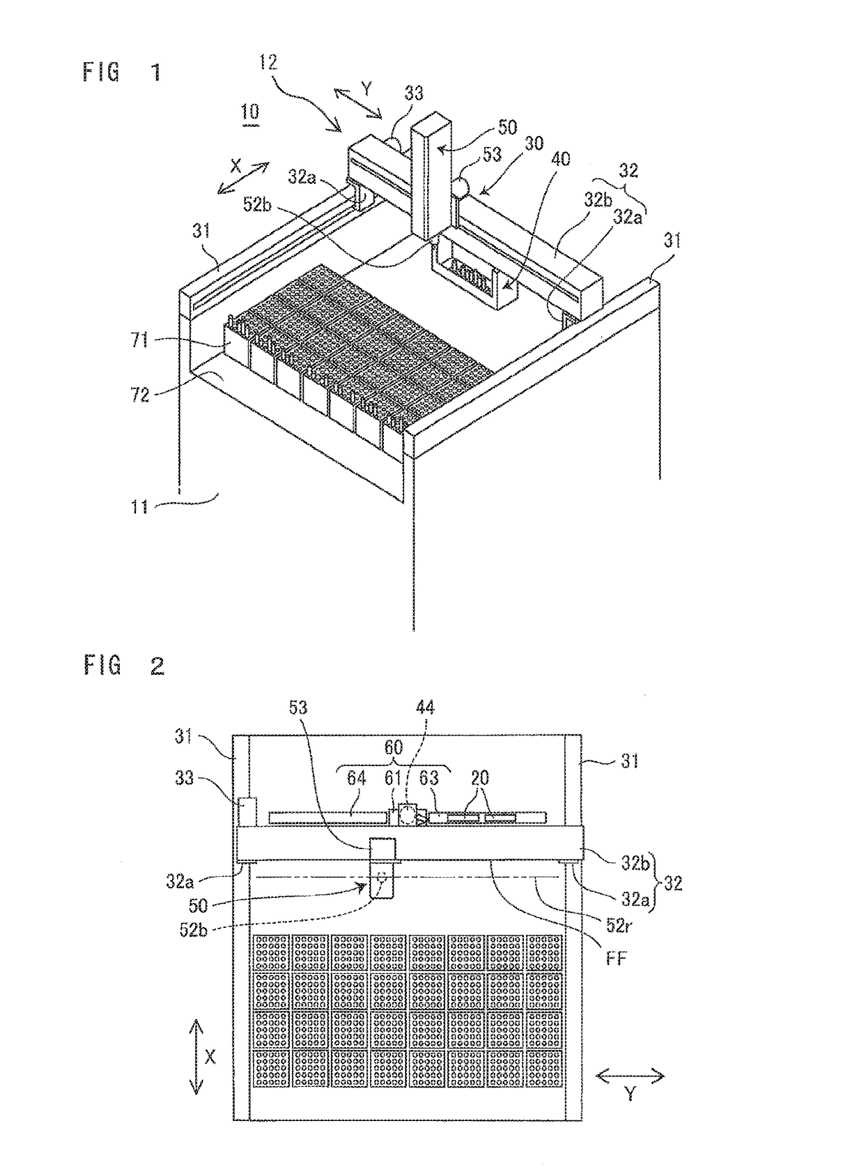
[0051]Preferred embodiments of a sorting apparatus according to the present invention will now be described with reference to the attached drawings.

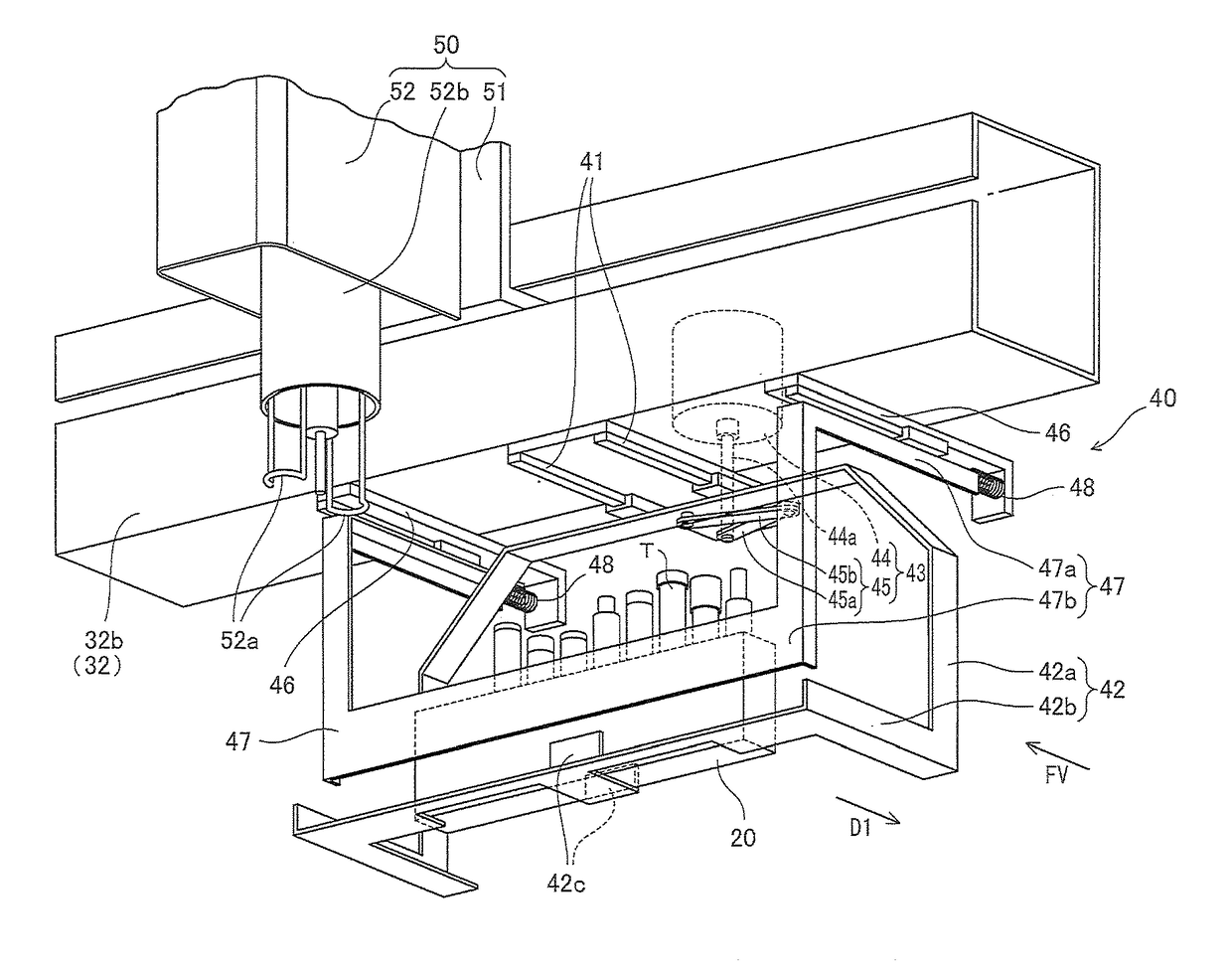
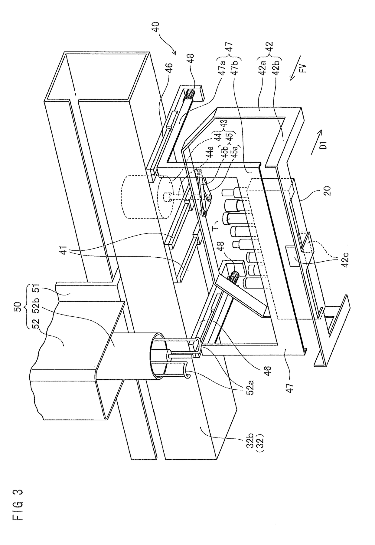
[0052]The sorting apparatus 10 shown in FIG. 1 is an apparatus that conveys a rack 20 (see FIG. 3 and FIG. 26) on which a plurality of blood collection tubes T (see FIG. 3) have been loaded and sorts the blood collection tubes T by removing the blood collection tubes T from the rack 20 and transferring such tubes to predetermined blood collection tube loading portions 70 (see FIG. 20).

[0053]The sorting apparatus 10 includes an apparatus base portion 11, a sorting device 12 installed on the base portion 11, a rack delivery device 60 (see FIG. 2) that delivers a rack 20, on which a plurality of blood collection tubes T have been loaded, to the sorting device 12, a sorting bench 72 on which sorting cassettes 71 equipped with a plurality of blood collection tube loading portions (or “vessel loading portions”) 70 are installed, a barcode read...


PUM

PropertyMeasurementUnit
movementaaaaaaaaaa
compatibilityaaaaaaaaaa
diameteraaaaaaaaaa

Abstract

A sorting apparatus includes: a sorting device receiving and transporting a rack carrying vessels and transferring vessels from the rack to predetermined vessel loading portions; and a delivery device delivering the rack to the sorting device. The sorting device includes: a rack receiving unit capable of moving reciprocally between a rack delivery position where the rack is delivered and a sorting position where the vessels are loaded into the predetermined vessel loading portions; a transfer machine transferring the vessels from the rack on the rack receiving unit to the predetermined vessel loading portions; and a transportation mechanism on which the rack delivering unit and the transfer machine are installed. The transportation mechanism is installed so as to be capable of moving in a transportation direction in which rack receiving unit moves reciprocally. The transfer machine is capable of moving in a direction perpendicular to the transportation direction.

Description

FIELD OF THE INVENTION[0001]The present invention relates to a sorting apparatus that sorts and conveys vessels, such as test tubes or blood collection tubes, which hold specimens to transfer destinations in accordance with conditions such as the specimen type and / or test type.DESCRIPTION OF THE RELATED ART[0002]Among known sorting apparatuses for classifying vessels holding specimens, there is a sorting apparatus including a loading bench as a sorting destination for the specimens and a header that moves above the loading bench, such header including a gripping unit for holding a bottomless cassette and a dropper unit for pressing out specimen vessels loaded onto the held cassette to below the held cassette (see Patent Document 1)[0003]Known sorting apparatuses also include a clinical test apparatus including a specimen introducing unit in which is set a rack for supporting vessels to which specimen identification numbers have been attached, a rack ID detection unit, a specimen ID ...

Claims


Application Information

Patent Timeline
Patent Type & Authority Patents(United States)
IPC IPC(8): G01N35/04B65G49/00G01N35/02
CPCB65G49/00G01N35/04G01N35/026G01N2035/0415G01N2035/0465Y10T436/114165
Inventor MURAKAMI, SEIGO
Owner SYSMEX CORP
Learn More