Releasable I-beam anchor

Active Publication Date: 2017-04-04
RELIANCE INDUSTRIES LIMITED
View PDF12 Cites 9 Cited by
  • Summary
  • Abstract
  • Description
  • Claims
  • Application Information

AI Technical Summary

Benefits of technology

[0017]In accordance with an aspect of the moveable bracket, the bracket body extends forwardly of the trigger housing, and the bracket further includes a wheel received on the body to rotate about an outer surface of the body. In this instance, the body can include front and rear flanges which extend from the bracket body on either side of the wheel. These front and rear flanges capture the wheel to substantially prevent the wheel from moving axially along the bracket body. The wheel can define an inner diameter only slightly greater than an outer diameter of the body to substantially limit the radial movement of the wheel relative to the body.

Problems solved by technology

However, concerns have arisen over the release (trigger) mechanisms for such I-beam anchors, including the ergonomics of the release / trigger mechanism and the ease to which the release mechanism may be inadvertently activated to release the anchor from engagement with the I-beam.

Method used


Image

  • Releasable I-beam anchor
  • Releasable I-beam anchor
  • Releasable I-beam anchor

Examples


Embodiment Construction

[0036]While the claimed invention will be described and disclosed here in connection with certain preferred embodiments, the description is not intended to limit the claimed invention to the specific embodiments shown and described here, but rather the claimed invention is intended to cover all alternative embodiments and modifications that fall within the spirit and scope of the invention as defined by the claims included herein as well as any equivalents of the disclosed and claimed invention.

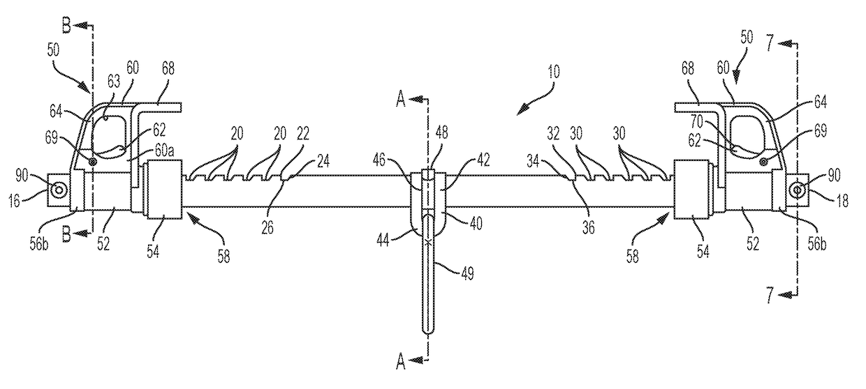
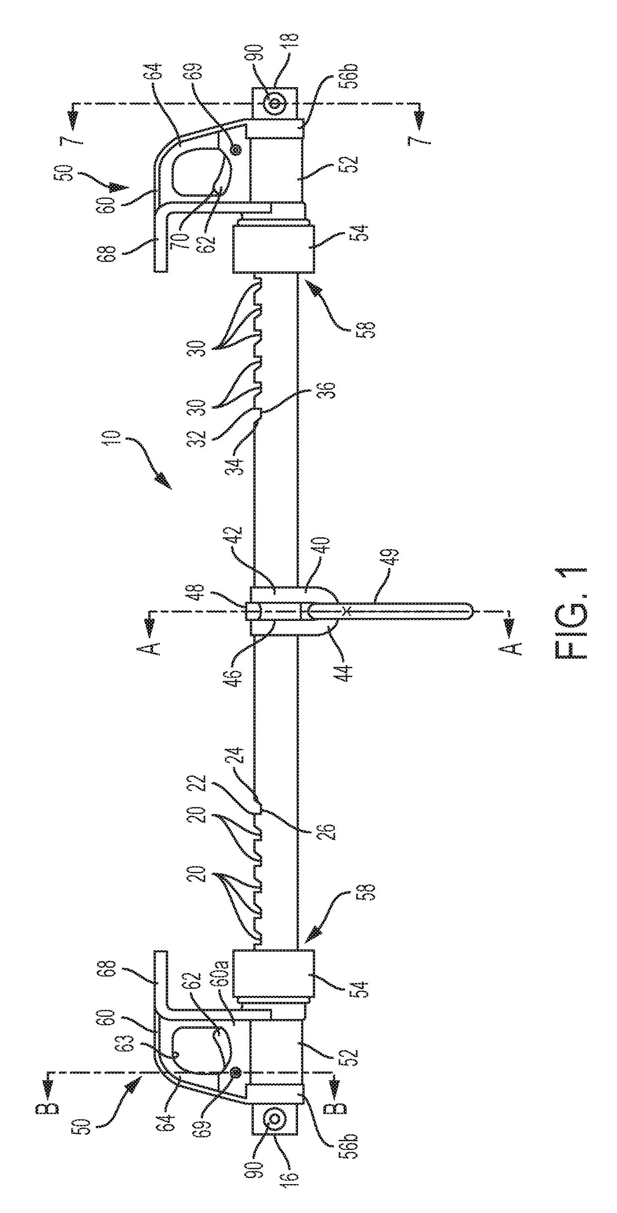
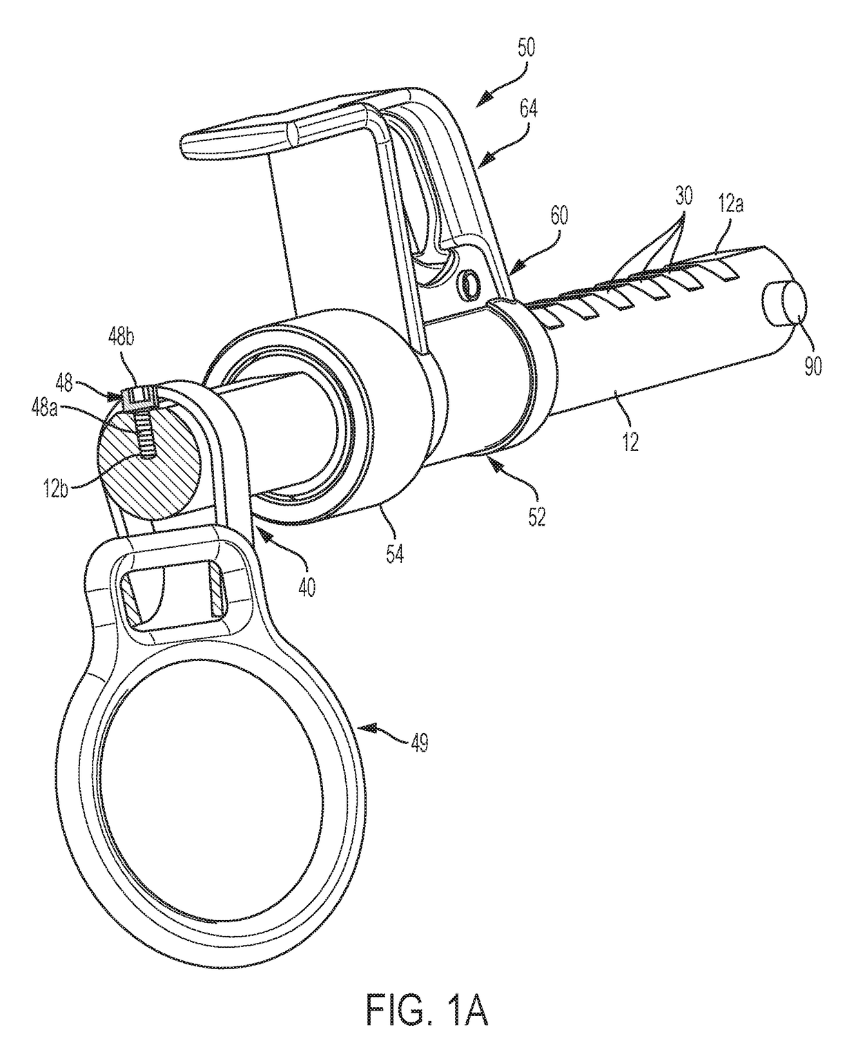
[0037]In referring to the drawings, an illustrative embodiment of a releasable I-beam anchor 10 is shown generally in FIGS. 1-9. As can be seen, the I-beam anchor 10 comprises a straight cross-beam 12 with a central portion 14, a first end 16, and a second end 18 opposite the first end 16. As seen in FIG. 2, the cross-beam 12 is generally cylindrical, but defines a flat top surface 12a. A hole 12b (FIG. 1A) at the approximate center of the cross-beam extends inwardly from the top surface 12a....


PUM


Abstract

An I-beam anchor for removably securing a fall protection member to an I-beam is disclosed. The I-beam anchor comprises a cross-beam, an anchor ring, and first and second brackets. The first bracket is positioned between a first end and center portion of the cross-beam and the second bracket positioned between a second end and center portion of the cross-beam. Each of the brackets comprises an inwardly directed flange spaced above the body of the brackets. At least the first bracket is a movable bracket and is movable along the cross-beam relative to the second bracket. The moveable bracket comprises a protected “quick release” mechanism that allows for the rapid engagement and disengagement of the anchor to the I-beam, in which the quick release mechanism is configured to minimize the chance of accidental or unintentional release.

Description

CROSS REFERENCE TO RELATED APPLICATIONS[0001]This application claims priority to U.S. application Ser. No. 62 / 169,886 filed Jun. 2, 2015, which is entitled “Releasable I-Beam Anchor” and which is incorporated herein by reference.STATEMENT REGARDING FEDERALLY SPONSORED RESEARCH OR DEVELOPMENT[0002]Not applicable.BACKGROUND OF THE INVENTION[0003]This invention relates generally to devices to mount safety harnesses, and more particularly to an apparatus that releasably attaches to an I-beam from which can be hung a safety harness to provide security to an individual wearing the harness at an elevated work position below the I-beam.[0004]It is not uncommon in the construction and building repair industries, and in other related industries, for individuals to work at elevated work positions, such as, for example during the construction or repair of the upper floors of a multistory building. A number of safety devices are used in such a situation. For example, safety harnesses and retract...

Claims


Application Information

Patent Timeline
Patent Type & Authority Patents(United States)
IPC IPC(8): E04G21/32A62B35/00A62B1/04E04G5/04
CPCE04G21/3242A62B1/04A62B35/0068E04G5/045E04G21/3204E04G21/3276
Inventor TSAOUSIS, DIMITRIOS
Owner RELIANCE INDUSTRIES LIMITED
Why Eureka
Try Eureka