System and method for corneal topography with flat panel display
a flat panel display and topography technology, applied in the field of vision diagnostics, can solve problems such as alignment errors, bad eyesight, and ocular aberrations that typically produce unwanted results
- Summary
- Abstract
- Description
- Claims
- Application Information
AI Technical Summary
Benefits of technology
Problems solved by technology
Method used
Image
Examples
first embodiment
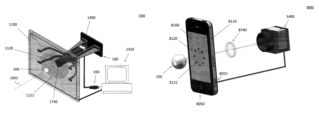
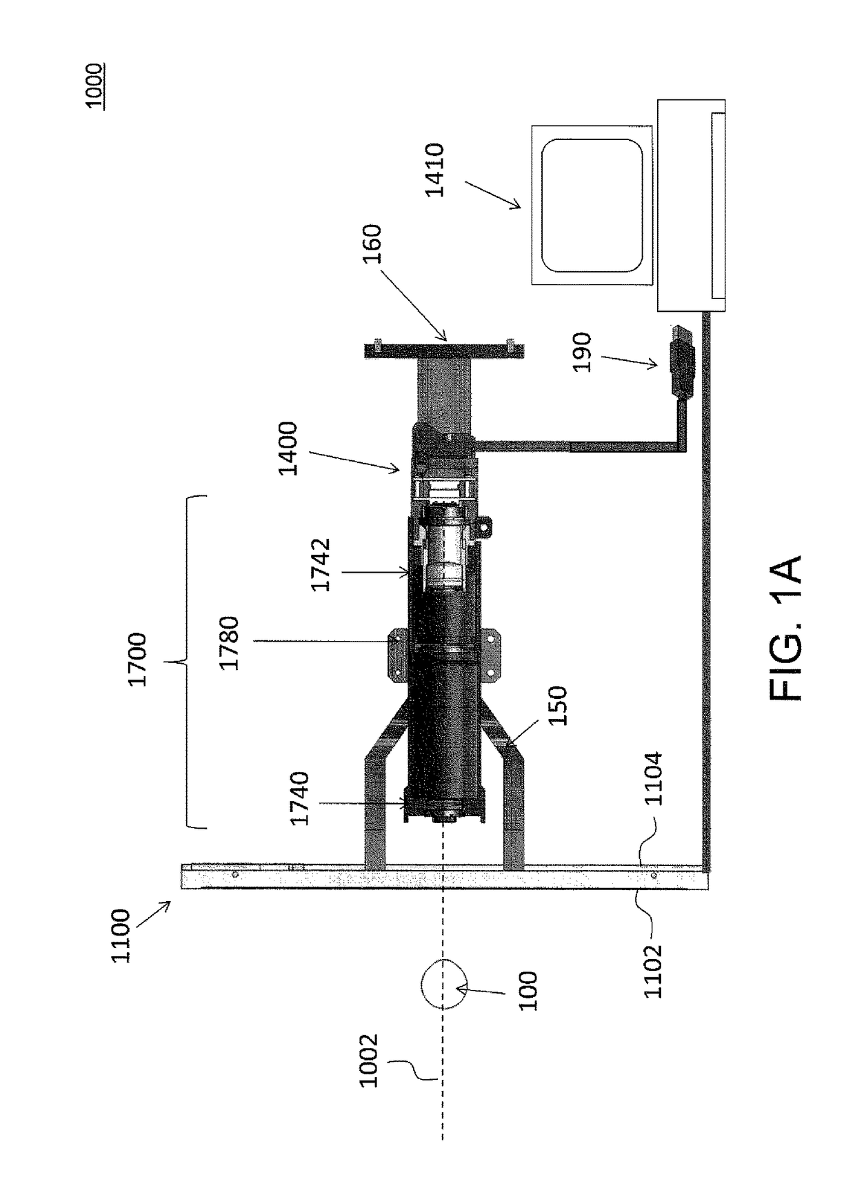
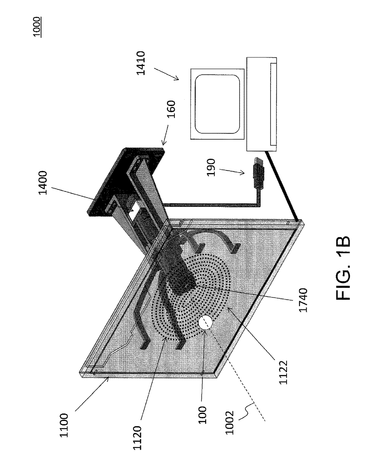
[0047]FIG. 1A shows a side view of a system 1000 for measuring corneal topography of an eye 100. FIG. 1B illustrates a perspective view of system 1000, and FIG. 1C illustrates a partial cutaway perspective view of system 1000.
[0048]System 1000 comprises a flat panel display 1100 having a first surface 1102 and a second surface 1104; a camera or detector array 1400; and an optical system 1700 disposed on a along a central axis 1002 passing flat panel display 1100. The eye 100 is disposed opposite first surface 1102 on a first side of flat panel display 1100 and optical system 1700 disposed opposite second surface 1102 on a second side of flat panel display 1100. Optical system 1700 comprises a first optical element (e.g., a lens) 1740, a structure including a telecentric aperture (or stop) 1780, and a second optical element (e.g., lens) 1742. It will be appreciated by those of skill in the art that the lenses 1742, 1744, or any of the other lenses discussed herein, may be replaced or...
second embodiment
[0081]FIG. 7 illustrates a perspective view of a system 7000 for corneal topography of an eye. System 7000 is constructed similarly to, and operates similarly to, system 1000 described above in detail, so only differences therebetween will be discussed.
[0082]System 7000 includes a flat panel display 7100 which has an aperture 7150 passing therethrough, wherein the reflected light from the cornea passes through aperture 7150 to optical system 1700. Accordingly, flat panel display 7100 need not be transparent. In various embodiments, flat panel display 7100 may comprise a liquid crystal display (LCD) device, an organic light emitting diode (OLED) display device, or other suitable display device.
third embodiment
[0083]FIG. 8 illustrates a side view of a system 8000 for measuring corneal topography of an eye. FIG. 9 illustrates a perspective view of system 8000. System 8000 is constructed similarly to, and operates similarly to, system 1000 described above in detail, so only differences therebetween will be discussed.
[0084]System 8000 includes a portable computing device 8050 with housing 8110 and flat display panel 8100. In some implementations, portable computing device 8050 may comprise a smart phone or a tablet device. In some implementations, flat panel display 8100 may be a touchscreen. In some implementations, flat panel display 8100 may be a transparent LCD display, similarly to flat panel display 1100. In some implementations, flat panel display 8100 may have an aperture passing therethrough, wherein the reflected light from the cornea of eye 100 passes through the aperture to optical system 1700. In some embodiments, portable computing device 8050 may include one or more processor(...
PUM
 Abstract
Description
Claims
Application Information
 - R&D
- Intellectual Property
- Life Sciences
- Materials
- Tech Scout
- Unparalleled Data Quality
- Higher Quality Content
- 60% Fewer Hallucinations
Browse by: Latest US Patents, China's latest patents, Technical Efficacy Thesaurus, Application Domain, Technology Topic, Popular Technical Reports.
© 2025 PatSnap. All rights reserved.Legal|Privacy policy|Modern Slavery Act Transparency Statement|Sitemap|About US| Contact US: help@patsnap.com


