Ophthalmologic imaging method, imaging apparatus, and non-transitory tangible medium

a technology of ophthalmologic imaging and imaging apparatus, applied in the field of ophthalmologic imaging methods, can solve the problems of taking time, affecting the image quality of the eye, so as to reduce the focus state change or imaging failure, and achieve the effect of reducing the change of focus state or imaging failur

Active Publication Date: 2017-04-11
CANON KK
View PDF22 Cites 0 Cited by
  • Summary
  • Abstract
  • Description
  • Claims
  • Application Information

AI Technical Summary

Benefits of technology

[0008]The present invention is made in view of the above-mentioned situation, and it is to perform the imaging more quickly so as to reduce a focus state change or an imaging failure due to an involuntary eye movement or a blind of an eye to be inspected.
[0010]The ophthalmologic imaging method according to one embodiment of the present invention compensates for a wavelength difference between observation light and imaging light when focus detection is finished. Thus, focus lens movement after depressing an imaging switch becomes unnecessary, and hence the imaging can be performed more quickly. Therefore, the focus state change or the imaging failure due to the involuntary eye movement or the blink of the eye to be inspected may be reduced.

Problems solved by technology

However, because it takes time to move the focus lens after depressing the imaging switch, it takes time from the depression of the imaging switch until the imaging by emitting the imaging light.
If an involuntary eye movement or a blink of the eye to be inspected occurs during the period, a focus state change or a fundus imaging failure may occur.

Method used


Image

  • Ophthalmologic imaging method, imaging apparatus, and non-transitory tangible medium
  • Ophthalmologic imaging method, imaging apparatus, and non-transitory tangible medium
  • Ophthalmologic imaging method, imaging apparatus, and non-transitory tangible medium

Examples


first embodiment

[0018]The present invention is described in detail based on an embodiment illustrated in FIG. 1 to FIG. 4.

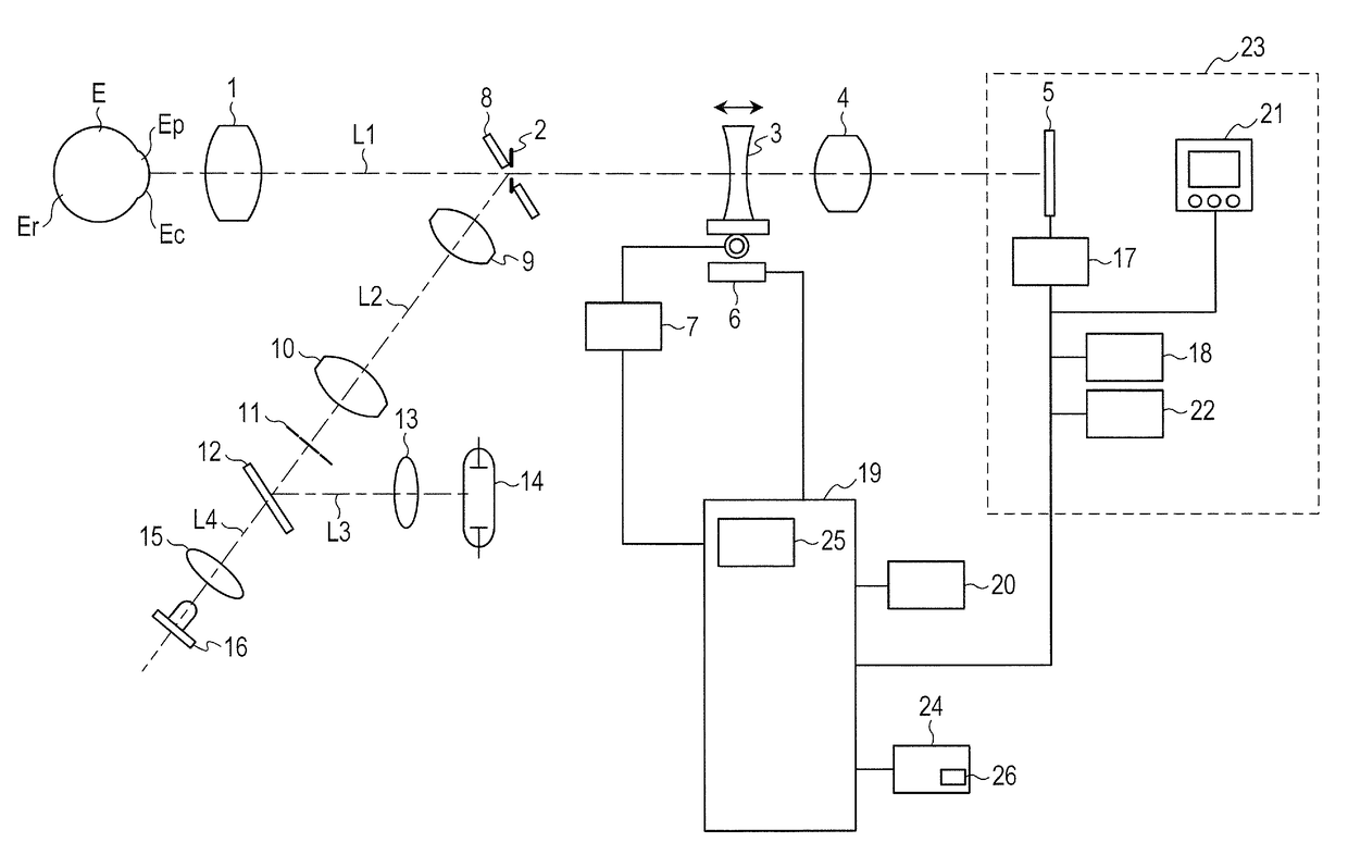
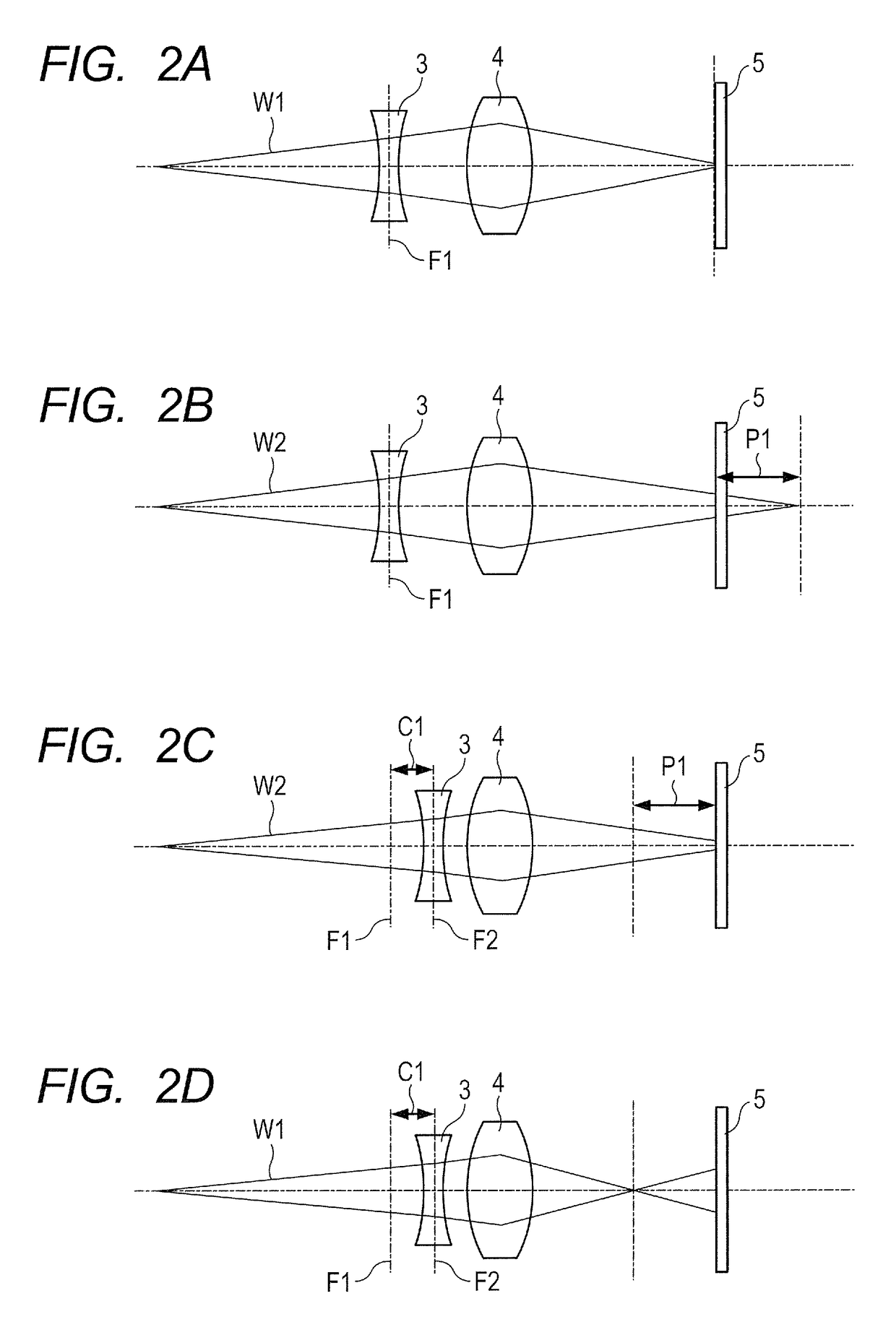
[0019]FIG. 1 is a structural diagram of a fundus camera. An objective lens 1 is disposed to be opposed to an eye to be inspected E. On an optical axis L1 of the objective lens 1, there are disposed an imaging stop 2, a focus lens 3, an imaging lens 4, and an image capture element 5 having sensitivity to visible light and infrared light. The objective lens 1 to the imaging lens 4 constitute an observation / imaging optical system, which constitutes a fundus image observation image capture unit together with the image capture element 5. Note that, the focus lens 3 is connected to a focus lens position detection portion 6 and a focus lens moving portion 7. The focus lens position detection portion 6 outputs a position of the focus lens 3 on the optical axis L1, and the focus lens 3 can be moved on the optical axis L1 by the focus lens moving portion 7.

[0020]On the other hand, a perfo...


PUM


Abstract

In order to perform observation and imaging by the same image capture unit, an ophthalmologic imaging method includes illuminating a fundus of an eye to be inspected with light having a first wavelength, guiding return light from the fundus to an image capture unit through a focus lens so as to obtain an in-focus position of the focus lens in accordance with the light having the first wavelength, illuminating the fundus with light having a second wavelength different from the first wavelength, and guiding return light from the fundus to the image capture unit through the focus lens so as to obtain an image of the fundus. The focus lens is moved to an in-focus position for the light having the second wavelength based on a wavelength difference between the light having the first wavelength and the light having the second wavelength.

Description

BACKGROUND OF THE INVENTION[0001]Field of the Invention[0002]The present invention relates to an ophthalmologic imaging method and apparatus that use a fundus camera or the like, which are used for a physical examination in a group checkup or a general checkup, and to a non-transitory tangible medium therefore.[0003]Description of the Related Art[0004]Conventionally, a fundus examination is performed in a group checkup such as a resident checkup or a company checkup. Usually in fundus imaging in the group checkup, non-mydriatic imaging is performed, which does not need mydriatics. In the non-mydriatic imaging, an examination room is darkened, or a simple darkroom is used so that the eye to be inspected is shielded from indoor light, and thus natural mydriasis of the eye to be inspected is urged for imaging.[0005]An ophthalmologic imaging apparatus that performs non-mydriatic fundus imaging includes an observation light source in an infrared wavelength range that usually does not cau...

Claims


Application Information

Patent Timeline
Patent Type & Authority Patents(United States)
IPC IPC(8): A61B3/14A61B3/12
CPCA61B3/14A61B3/12
Inventor OGURA, HIRAKU
Owner CANON KK
Why Eureka
Try Eureka