Unlock instant, AI-driven research and patent intelligence for your innovation.

Shower apparatus

a technology for showering equipment and shower heads, which is applied in the direction of spraying apparatus, spray nozzles, liquid spraying apparatus, etc., can solve the problems of impaired comfort feeling of the user of the showering equipment, unstable pulsation, and non-uniform flow rate distribution, and achieve stable pulsation, stable pulsation, and uniform channel resistance

Active Publication Date: 2017-04-11
TOTO LTD
View PDF10 Cites 1 Cited by
  • Summary
  • Abstract
  • Description
  • Claims
  • Application Information

AI Technical Summary

Benefits of technology

The shower apparatus described in this patent discharges bubbly water, which creates a voluminous feel while reducing water usage. The main water stream is attracted to the swirl by negative pressure, resulting in stable pulsation of the bubbly water. The opening area of the nozzle holes is made uniform among all the small spaces, allowing for stable pulsation and reduced channel resistance. The small spaces have a uniform shape, resulting in a uniform flow rate of backflow water and a uniform distribution of swirl size. Overall, the shower apparatus creates a more stable and comfortable shower experience with reduced water usage.

Problems solved by technology

Meanwhile, such shower apparatus also reduces a stimulus sensation felt by a user when discharged bubbly water hits skin of the user, and this has been presented a problem in that a comfort feeling of the user of the shower apparatus is impaired.
However, in a shower apparatus having the configuration described in JP2012-187346 A, the phase and period of pulsation provided to bubbly water may differ depending on the position of a nozzle hole, resulting in unstable pulsation.
However, for example, water streams ejected from the throttle unit toward different directions may interfere with each other, or some water streams may collide with inner wall surfaces of the shower apparatus, resulting in a non-uniform distribution of the flow rate of the backflow water that returns from the direction of the outer circumference to the swirl chamber.
Pulsations with different phases may temporarily offset each other, and this causes unstable pulsation as a whole.
Regarding the shower apparatus configured in such manner, it is considered that, due to, for example, a situation in which water streams ejected in different directions from the throttle unit interfere with each other or a situation in which some water streams collide with inner wall surfaces of the shower apparatus, backflow water that returns from the water discharge unit side toward the throttle unit may not have a uniform flow-rate distribution, as a whole, indicating that the flow rate varies depending on the direction in which the stream returns.
As a result, it can be considered that bubbly water is not imparted with uniform pulsation, resulting in unstable pulsation.

Method used


Image

  • Shower apparatus
  • Shower apparatus
  • Shower apparatus

Examples


Embodiment Construction

[0042]Embodiments of the present invention will now be described below with reference to the accompanying drawings. To facilitate understanding of the description, the same components in the respective drawings are denoted by the same reference numerals whenever possible and repetitive description thereof will be omitted.

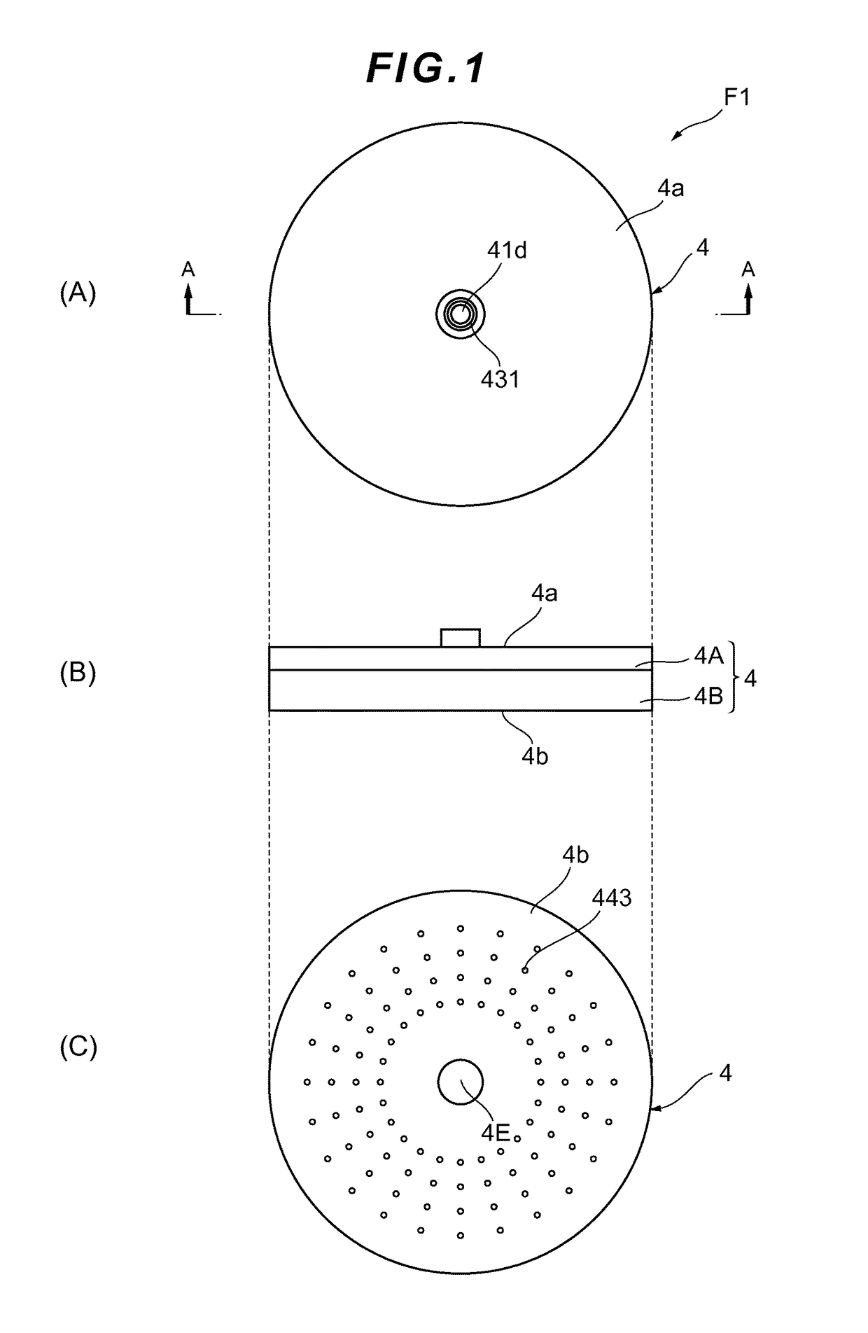
[0043]A shower apparatus, which is an embodiment of the present invention, will now be described with reference to FIGS. 1A, 1B and 1C, which are diagrams showing a shower apparatus F1 according to an embodiment of the present invention, in which FIG. 1A is a plan view, FIG. 1B is a side view, and FIG. 1C is a bottom view. As shown in FIG. 1A, the shower apparatus F1 is constituted by a body 4 which forms a circular shape in a top view, and a water supply port 41d is formed in a top face 4a of the shower apparatus F1 (body 4). The water supply port 41d is an inlet for water that is supplied from the outside.

[0044]As shown in FIG. 1B, the body 4 of the shower apparat...


PUM


Abstract

In this shower apparatus, a part of an internal space thereof closer to the outer circumference thereof than an aeration unit is defined as a plurality of small spaces, and all of the small spaces have a uniform channel resistance.

Description

BACKGROUND[0001]Field of the Invention[0002]The present invention relates to a shower apparatus that discharges aerated bubbly water.[0003]Description of Related Art[0004]A shower apparatus which discharges bubbly water by aerating water using a so-called ejector effect is known. Such shower apparatus can reduce the amount of water usage via aeration. Meanwhile, such shower apparatus also reduces a stimulus sensation felt by a user when discharged bubbly water hits skin of the user, and this has been presented a problem in that a comfort feeling of the user of the shower apparatus is impaired.[0005]In view of the above, the applicant has proposed the shower apparatus described in JP2012-187346 A. The shower apparatus described in JP2012-187346 A periodically varies the amount of air mixed into the water, whereby pulsation is provided to bubbly water to be discharged. Such pulsation is felt by the user of such shower apparatus as a stimulus sensation. As a result, a stimulus sensatio...

Claims


Application Information

Patent Timeline
Patent Type & Authority Patents(United States)
IPC IPC(8): B05B7/10B05B1/08B05B1/18B05B7/04
CPCB05B1/083B05B1/08B05B1/18B05B7/0425
Inventor HAYATA, SHUHEITAKEDA, KOJIUEMURA, YASUFUMIUKIGAI, KIYOTAKENAGATA, KATSUYA
Owner TOTO LTD