Marine hull and marine vessel

a marine hull and hull technology, applied in the field of marine hulls, can solve the problems of plastic boats, hull risks cracking, and large (less than 10 m) boats of such a lightweight structure, and achieve the effect of improving the marine hull and large resistance to permanent deformation

Active Publication Date: 2017-04-11
SSY IP TECH LLC
View PDF34 Cites 3 Cited by
  • Summary
  • Abstract
  • Description
  • Claims
  • Application Information

AI Technical Summary

Benefits of technology

[0009]Thus, the present invention is based on the understanding that by manufacturing a part of the framework of the hull, at least one longitudinal reinforcement, resiliently, the same will absorb strong external load without the hull plate obtaining permanent deformations.

Problems solved by technology

However, large (greater than 10 m) as well as small (less than 10 m) boats of such a lightweight structure are impaired by certain disadvantages.
A large disadvantage of plastic boats is that they are relatively fragile in relation to size and weight, and thereby the hull risks cracking in heavy groundings or if the boat bumps into cliffs upon mooring in natural harbour.
Another disadvantage of plastic boats is that they require much care and maintenance, for instance cleaning, under water painting, waxing, polishing, etc., to prevent the plastic from ageing and crackling.
However, the ageing of the plastic cannot entirely be prevented and the air, the water, UV radiation, and aquatic organisms deteriorate the properties of the plastic already after a few years.
Marine hulls of plastic have relatively large tolerances, approximately ±1% in length and width, as well as are not stable in shape; this entails expensive and highly time-consuming fitting work of the fixtures and other structures of the marine vessel.
A large disadvantage of boats manufactured from light metal, such as aluminium, is that the hulls of these boats have to be welded together from several panels, generally single-curved panels, which limits the hydrodynamic properties of the marine vessel.
The welding seams also risk cracking upon grounding or the like.
Aluminium boats also have the disadvantage that, in course of time, a total fatigue of the material occurs.
In addition, boats of light-metal hulls easily buckle due to external stress, because the hull plate has a low buckling load limit at the same time as the framework, or set of longitudinal reinforcements and transverse reinforcements, of the boat that carries the hull plate is entirely rigid and non-compliant.
These deformations imply not only an aesthetic problem but also a hydrodynamic problem, with decreasing maximum speed and manoeuvrability as a consequence.
Similar to marine hulls manufactured from plastic, marine hulls manufactured from aluminium also have relatively large tolerances, approximately ±1% in length and width, which entails expensive and highly time-consuming fitting work of the fixtures and other structures of the marine vessel.
Even if said boats withstand large external stresses, they risk, similar to aluminium boats, getting permanent deformations.
Another large disadvantage of this type of steel boats is that they have a great weight in relation to their size and thereby consume much fuel upon propulsion, which makes them less suitable for private use.

Method used


Image

  • Marine hull and marine vessel
  • Marine hull and marine vessel
  • Marine hull and marine vessel

Examples


first embodiment

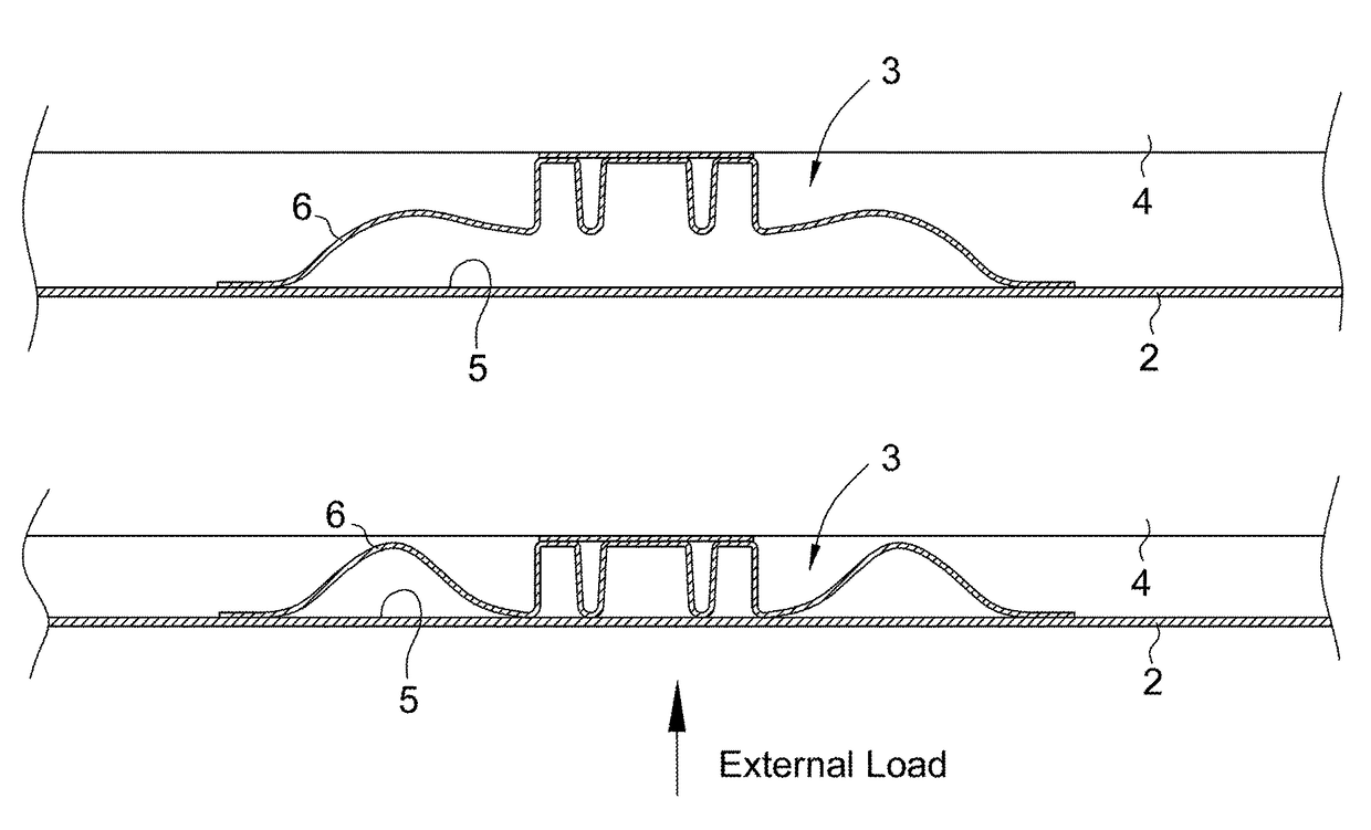
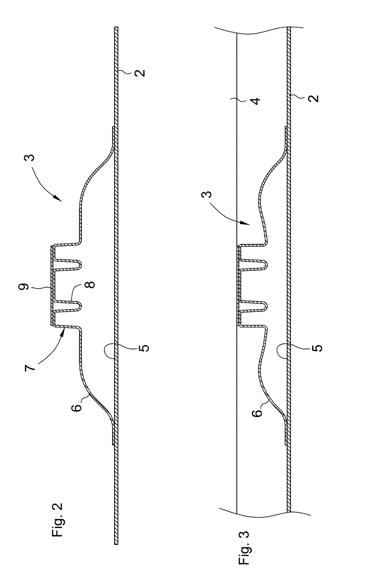
[0028]Reference is made now to FIGS. 2 and 3, in which there is shown a schematic cross-sectional view of a part of the marine hull 1 according to the invention having the longitudinal reinforcement 3 in an unloaded and partly compressed state, respectively.

[0029]The longitudinal reinforcement 3 comprises at least one resilient segment 6 arranged to spring in the direction transverse to the thickness of the hull plate 2, said resilient segment 6 preferably being longitudinal along the longitudinal reinforcement 3. In the embodiment shown, the resilient element 6 has an extended S-shape. Said resilient segment 6, or the longitudinal reinforcement 3, is arranged to bottom upon a compression that is more than 10 mm and less than 50 mm. In other words, upon an applied external force, the hull plate 2 is pressed inward at the same time as the resilient segment 6 springs to absorb the applied external force and thereby permanent deformation of the hull plate 2 is prevented.

[0030]Preferab...

second embodiment

[0033]Reference is now made to FIG. 4, in which an alternative, second embodiment is shown of the longitudinal reinforcement 3 in an unloaded state.

[0034]In this embodiment, the rigid segment 7 comprises, in the same way as in the first embodiment, in cross-sectional a wave-shaped, or serpentine-shaped, plate segment 8 that preferably is connected to a flat strip plate 9. However, with the difference that the in cross-sectional wave-shaped plate segment 8 does not constitute part of the plate having longitudinal bendings that is the major part of the longitudinal reinforcement 3. Instead, the two resilient segments 6 are interconnected by means of a straight intermediate section 10, the wave troughs of the in cross-sectional wave-shaped plate segment 8 being connected to said intermediate section 10.

[0035]The longitudinal reinforcement 3 should preferably have such a shape that possibly condensation on the inside 5 of the hull plate 2 does not risk being accumulated.

Feasible Modific...


PUM


Abstract

A marine hull including a hull plate manufactured from metal, a set of longitudinal reinforcements and a set of transverse reinforcements, at least one longitudinal reinforcement of the set of longitudinal reinforcements being arranged between the hull plate and at least one transverse reinforcement of the set of transverse reinforcements, and being connected to an inside of the hull plate. The marine hull is characterized in that the hull plate has a thickness that is less than 10 mm, and that the at least one longitudinal reinforcement is manufactured from the same metal as the hull plate and comprises at least one resilient segment arranged to spring in the direction transverse to the thickness of the hull plate, and that the resilient segment is arranged to bottom upon a compression that is more than 10 mm and less than 50 mm.

Description

CROSS-REFERENCE TO RELATED APPLICATIONS[0001]This application is a U.S. National Phase Patent Application of PCT Application No. PCT / SE2013 / 050344, filed Mar. 27, 2013, which claims priority to Swedish Patent Application No. 1250361-1, filed Apr. 11, 2012, each of which is incorporated by reference herein in its entirety.TECHNICAL FIELD OF THE INVENTION[0002]The present invention relates generally to a marine hull manufactured from metal in the form of a lightweight structure for marine vessels. In particular, the present invention relates to a marine hull comprising a hull plate manufactured from metal, a set of longitudinal reinforcements and a set of transverse reinforcements. At least one longitudinal reinforcement of said set of longitudinal reinforcements is arranged between the hull plate and at least one transverse reinforcement of said set of transverse reinforcements, and is connected to an inside of the hull plate. In a second aspect, the present invention relates to a ma...

Claims


Application Information

Patent Timeline
Patent Type & Authority Patents(United States)
IPC IPC(8): B63B3/36B63B3/26B63B43/18B63B3/32
CPCB63B3/36B63B3/26B63B43/18B63B3/32B63B3/24B63B2003/265
Inventor ROSEN, HAKAN
Owner SSY IP TECH LLC
Why Eureka
Try Eureka