
PLL frequency selection

a phase lock and frequency technology, applied in the direction of digital transmission, transmission path sub-channel allocation, electrical equipment, etc., can solve the problems of adc and hence the receiver's performance degradation, waste of time for re-synchronizing the pll, and the receiver's performance in terms of signal-to-noise ratio (snr)

Active Publication Date: 2017-04-18
TELEFON AB LM ERICSSON (PUBL)
View PDF12 Cites 0 Cited by
  • Summary
  • Abstract
  • Description
  • Claims
  • Application Information

AI Technical Summary

Benefits of technology

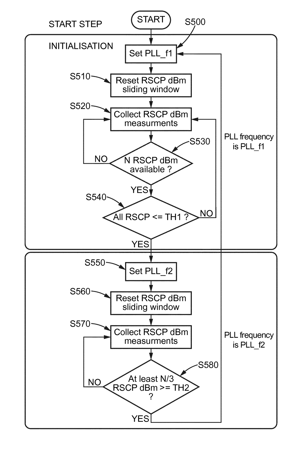
[0011]Thus, in a receiver embodying the principles of such a frequency evasion scheme, a PLL frequency change decision is triggered based on a plurality of signal measurements using two different signal thresholds for alternatively changing the PLL frequency from one given value to at least one different value, thus with an hysteresis effect. Such control scheme for changing the PLL frequency has the advantage of avoiding wrong PLL frequency decisions of changing, and “ping-pong” effect.
[0012]In one embodiment, when all signal measurements of the first set of signal measurements are beyond the first threshold, the PLL frequency change from the first value to the second value is triggered by an event based on the prior comparison. The PLL frequency is set by default to the first value. The second value of the PLL frequency may be chosen from a list of given frequencies. This allows easier implementation using, for instance, a set of discrete control values respectively associated with each of the frequencies, which may be stored in a data register.
[0013]The first threshold may be a signal level below which numerous spurs would ultimately lead to unacceptable degradation of performances of the receiver. This has the advantage of guarantying that the PLL frequency change is made only when the receiver is operated in a range of operation that is the most sensitive to spurs. The likelihood of wrong PLL frequency change can thus be reduced.
[0015]In accordance with a feature of the proposed solution, the set of signal measurements is fixed to correspond to an integer N of signal measurements, greater than 1, collected over the sliding window. This helps guarantying that variability of the signal over a sufficient period is considered before triggering the PLL frequency change.

Problems solved by technology

These unwanted signals, known as spurs, may also be translated within the IF frequency band, thus resulting in a degradation of the receiver's performance in terms of signal-to-noise ratio (SNR).
These unwanted signals, also known as spurs in that context, may affect the accuracy of the digital output signal resulting in a degradation of the ADC and hence of the receiver's performance.
This technique, known as frequency evasion, however presents some drawbacks because wrong PLL frequency change decisions can be made which may result in a waste of time for re-synchronizing the PLL.
All of this leads to a degradation of the receiver performance.

Method used


Image

  • PLL frequency selection
  • PLL frequency selection
  • PLL frequency selection

Examples


Embodiment Construction

[0020]In the drawings, like reference numbers designate like parts in various Figures. Expressions such as “comprise”, “include”, “incorporate”, “contain”, “is” and “have” are to be construed in a non-exclusive manner when interpreting the description and its associated claims, namely construed to allow for other items or components that are not explicitly defined also to be present. Reference to the singular is also to be construed in being a reference to the plural, and vice versa.

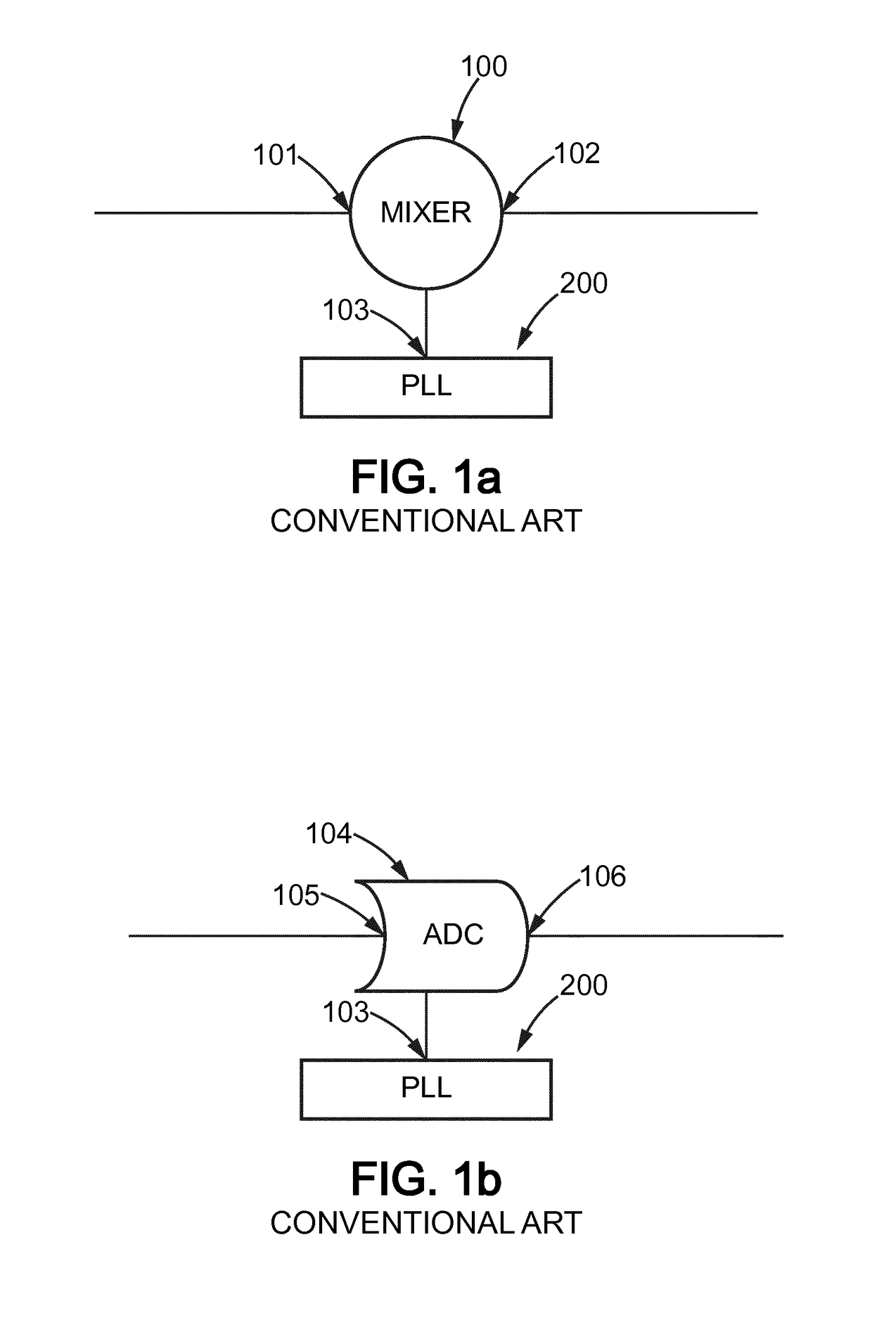
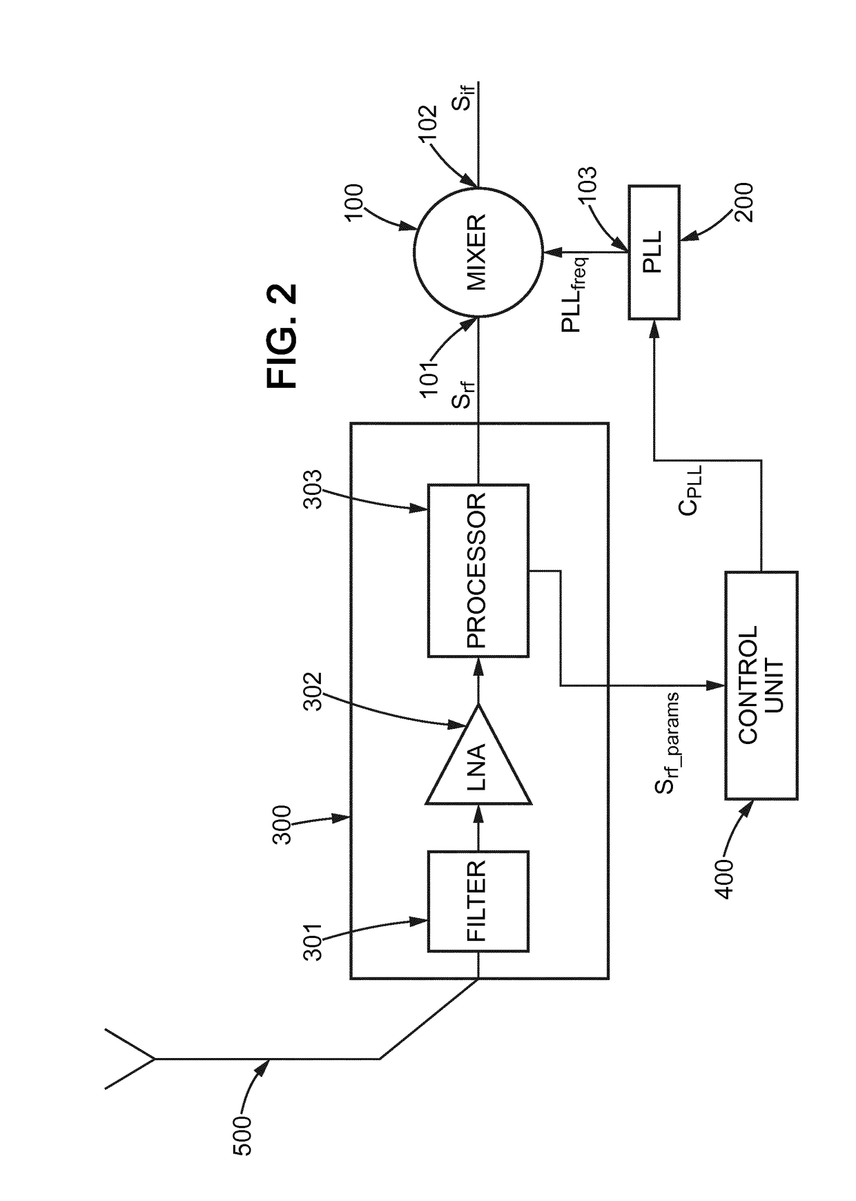
[0021]FIG. 1a is a block diagram illustrating a conventional art usage of the PLL technique associated with a mixer 100. In this example, a PLL 200 is configured for generating one or many accurate signal oscillation frequencies at the output 103 of the PLL from one or more reference sources that would be combined with the input 101 of the mixer 100. This would generate a mixed output signal at the output 102 of the mixer 100. In this example, the oscillation frequencies generated by operation of the PLL...


PUM


Abstract

A method of controlling a frequency selection of a PLL used in cooperation with a device of a wireless communication network, such as a Universal Mobile Telecommunication System (UMTS) network, the method comprising: —receiving a first set of signal measurements; —comparing the first set of signal measurements with a first threshold and, selectively switching the PLL frequency from a first value to a second value as a result of the comparison of the first set of signal measurements with the first threshold; —further receiving a second set of signal measurements; and, —comparing the second set of signal measurements with a second threshold, different from the first threshold, and selectively switching the PLL frequency from the second value to the first value as a result of the comparison of the second set of signal measurements with the second threshold.

Description

FIELD OF THE INVENTION[0001]This invention relates to phase locked loops (PLL) in wireless communication networks and, more particularly, to a method and a device for controlling PLL frequency selection allowing reduction of spurious frequencies in a serving cell of such a network.BACKGROUND OF THE INVENTION[0002]The PLL technique has been around for a long time and has a wide variety of applications in wireless communication networks. It is frequently used for implementing operations such as demodulation, decoding, synchronisation, frequency synthesis or sampling.[0003]In a frequency synthesiser, for instance, the PLL technique may be used for generating one or many accurate signal oscillation frequencies from one or more reference sources. In e.g. a radiofrequency (RF) receiver, a PLL may be associated with a signal mixer. A signal mixer is a circuit capable of translating a signal from a given frequency within the RF band to another, lower frequency known as an intermediate frequ...

Claims


Application Information

Patent Timeline
Patent Type & Authority Patents(United States)
IPC IPC(8): H04L5/00H04W72/04H04B1/10
CPCH04B1/1027H04L5/0037H04W72/0453
Inventor DEMAJ, PIERRETOMATIS, FABRIZIO
Owner TELEFON AB LM ERICSSON (PUBL)
Learn More