Electric tool

a technology of electric tools and electric motors, applied in the field of hand-held electric tools, can solve the problems of less commonly available 36v batteries with lower output voltage ratings, more commonly available batteries with less output voltage ratings, and often cost more to produce and sell. , to achieve the effect of enhancing operability and/or usability, and easy attachment and removal

Active Publication Date: 2017-04-25
MAKITA CORP
View PDF28 Cites 15 Cited by
  • Summary
  • Abstract
  • Description
  • Claims
  • Application Information

AI Technical Summary

Benefits of technology

[0006]An objective of the present invention is to enhance general usability of an electric tool while reducing the associated battery cost for the same by, for example, configuring the electric tool, such as an angle drill and / or a disc grinder, to accept multiple 18V batteries to provide similar results as a traditional angle drill and / or a disc grinder requiring, for example, a single 36V battery power source.
[0009]As described above, an electric tool of a 36V specification may be used with two 18V batteries that a user may have as spare batteries, thus avoiding the need to obtain a single, dedicated 36V battery. Thus, an electric tool of higher output, i.e. 36V, may be used with readily accessibly 18V batteries, thus potentially reducing the costs associated with purchasing the often rarer, and more expensive, 36V battery. As a result, the convenience and / or usability of a high-output electric tool may be enhanced.
[0011]In an embodiment, an electric tool has a plurality of battery attachment portions, to which batteries may be attached, such that the longitudinal direction of the plurality of battery attachment portions extends vertically along a spindle axis. The batteries may be attached to and / or detached from the plurality of battery attachment portions by sliding the batteries vertically into their corresponding battery attachment portions. Further, since the batteries may be attached in a lengthwise fashion with their longitudinal direction oriented vertically, the electric tool may be relatively compact when viewed in a width-wise direction.
[0013]In an embodiment, an electric tool has a plurality of battery attachment portions to which batteries can be attached to and detached from by sliding the batteries in a vertical direction along a spindle axis. The batteries may be easily attached to and detached from the battery attachment portions. In this respect, the electric tool may satisfy needs associated with general operability and usability.
[0014]In an embodiment, an electric tool has a plurality of battery attachment portions to which batteries may attach. The plurality of battery attachment portions may have attachment surfaces oriented to face each other. Thus, batteries may be attached to the plurality of battery attachment portions in various orientations, i.e. horizontally and / or vertically. Such battery attachment flexibility as provided by the plurality of battery attachment portions may enhance operability and / or usability regarding attachment and detachment of the batteries to their corresponding battery attachment portions.
[0016]Given that the electric power tool of the above-described embodiment includes two battery attachment portions, two rechargeable batteries may be inserted into their corresponding battery attachment portions to thus be attached to the electric power tool. In such a configuration as described here, power supplied to electric power tool may have a relatively high voltage and / or large supply capacitance when necessary and / or desirable. As described earlier in connection with the electric tool in accordance with the first embodiment, the two battery attachment portions may be respectively arranged on the housing that forms the exterior member in symmetry and / or alignment with respect to, for example, a central axis of the motor shaft. This may achieve a balance in weight increased through the attached rechargeable batteries. Such an arrangement and / or configuration of the batteries on the housing as described here, i.e. in sequence and / or in parallel, may allow for uniform weight distribution across the central axis of the motor shaft of the disc grinder, and thus suppress and / or reduce deterioration in the maneuverability of the electric tool, while held in hand of an operator and used to machine, for example, a surface.

Problems solved by technology

Although 36V batteries may be desirable to power specific appliances demanding such a voltage, for example, such 36V batteries often cost more to produce and sell than other, more commonly available batteries with lower output voltage ratings.

Method used


Image

  • Electric tool
  • Electric tool
  • Electric tool

Examples


first embodiment

[0139]In the following, a first embodiment of the present invention will be described in further detail with reference to FIGS. 47 through 53. In FIG. 47, reference numeral 110 denotes a disc grinder in correspondence to an electric tool in accordance with the present invention. FIG. 48 is a cut-away view of the disc grinder 110, i.e. where the disc grinder 110 is cut in half across an imaginary axis extending from a front to a rear of the disc grinder 110 as shown by the legend of FIG. 48. FIG. 49 is a plan view (i.e. a diagrammatical view), as seen from below, of the disc grinder shown in FIG. 47. FIG. 50 is a plan view, as seen from behind (i.e., the rear), of the disc grinder shown in FIG. 47. FIG. 51 is a detailed perspective view of a rechargeable battery 180 inserted into and / or attached to a battery attachment portion through, for example, sliding. FIG. 52 is an enlarged plan view of portion (LII) of FIG. 49, illustrating a battery terminal connection portion. FIG. 53 is a c...

second embodiment

[0163]Next, the second and third embodiments, which may be modifications of the first embodiment described above, will be described in further detail with reference to FIGS. 54 through 59. In the second and third embodiments, only the arrangement of the battery attachment portions 160 Differs from that of the disc grinder 110 of the first embodiment. Thus, portions of the disc grinder 110 which are formed substantially in the same manner as in the first embodiment are indicated by like reference numerals in the drawings, and a description thereof will be omitted.

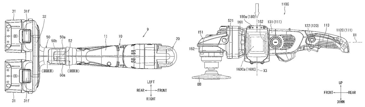
[0164]First, a disc grinder 110A according to the second embodiment will be described. FIG. 54 illustrates a side view of the disc grinder 110A of the second embodiment. FIG. 55 is a plan view, as seen from below, of the disc grinder 110A shown in FIG. 54. FIG. 56 is a plan view, as seen from behind, of the disc grinder 110A shown in FIG. 54. As shown in FIGS. 54 through 56, the battery attachment portions 160 A of the secon...

third embodiment

[0171]Next, a disc grinder 110B in accordance with the third embodiment will be described in further detail. FIG. 57 is a side view illustrating the disc grinder 110B of the third embodiment. FIG. 58 is a plan view, as seen from below, of the disc grinder 110B shown in FIG. 57. FIG. 59 is a plan view, as seen from behind, of the disc grinder 110B shown in FIG. 57. As shown in FIGS. 11 through 13, the battery attachment portions 160B of the third embodiment may also be arranged on the lower connecting portion 116 of the grip housing 112, the same as the battery attachment portions 160 of the first embodiment.

[0172]In further detail, a first battery attachment portion 160Ba and a second battery attachment portions 160Bb may be arranged in parallel and be deviated in right-to-left direction with respect to the lower connecting portion 116. Nevertheless, the first battery attachment portion 160Ba and the second battery attachment portion 160Bb may be arranged such that the connection te...


PUM


Abstract

An electric tool, such as an angle driver, has a main tool body with a front portion and a rear portion positioned opposite to the front portion. The main tool body houses a motor configured to receive electricity to function as a drive source. A gear head is coupled with the front portion of the main tool body wherein the gear head has a spindle in communication with a motor axis of the motor via mesh-engagement of bevel gears associated with the motor axis. The spindle has with a cutter tool accessory attached thereto such that rotation of the motor axis produces a commensurate rotation of the cutter tool accessory. Battery attachment portions are associated with the rear portion of the main tool body and are configured to receive a corresponding set of batteries that provide electricity to power the motor.

Description

CROSS-REFERENCE TO RELATED APPLICATIONS[0001]The present application is a continuation application based on, and claims priority to, PCT Application No. PCT / JP2013 / 082964, filed Dec. 9, 2013, which claims priority to Japanese Patent Application No. 2013-018881, filed Feb. 1, 2013, and PCT Application No. PCT / JP2013 / 084841, filed Dec. 26, 2013, which claims priority to Japanese Patent Application No. 2013-018868, filed Feb. 1, 2013, all of which are incorporated herein in their entireties by reference.TECHNICAL FIELD[0002]The present invention generally relates to a hand-held electric tool such as an electric drill, i.e. an angle drill used for various types of drilling operations, and / or a disc grinder, which may be adapted to grind and / or machine a surface to produce a desired effect. More particularly, the present invention may include various embodiments directed to the attachment and / or coupling of one or more batteries adapted to engage with the electric tool such that the elec...

Claims


Application Information

Patent Timeline
Patent Type & Authority Patents(United States)
IPC IPC(8): B25F5/02B24B23/00H02J7/00
CPCH02J7/00H02J7/0045B25F5/02H02J7/0063H02J7/0013B24B23/028B24B23/02
Inventor ITO, MIYABIKUMAGAI, RYUNOSUKESUGIURA, SHINMIZUTANI, AKIRAKAWAKAMI, TAKAHIRO
Owner MAKITA CORP
Why Eureka
Try Eureka