Electric tool
a technology of electric tools and electric motors, applied in the field of hand-held electric tools, can solve the problems of less commonly available 36v batteries with lower output voltage ratings, more commonly available batteries with less output voltage ratings, and often cost more to produce and sell. , to achieve the effect of enhancing operability and/or usability, and easy attachment and removal
- Summary
- Abstract
- Description
- Claims
- Application Information
AI Technical Summary
Benefits of technology
Problems solved by technology
Method used
Image
Examples
first embodiment
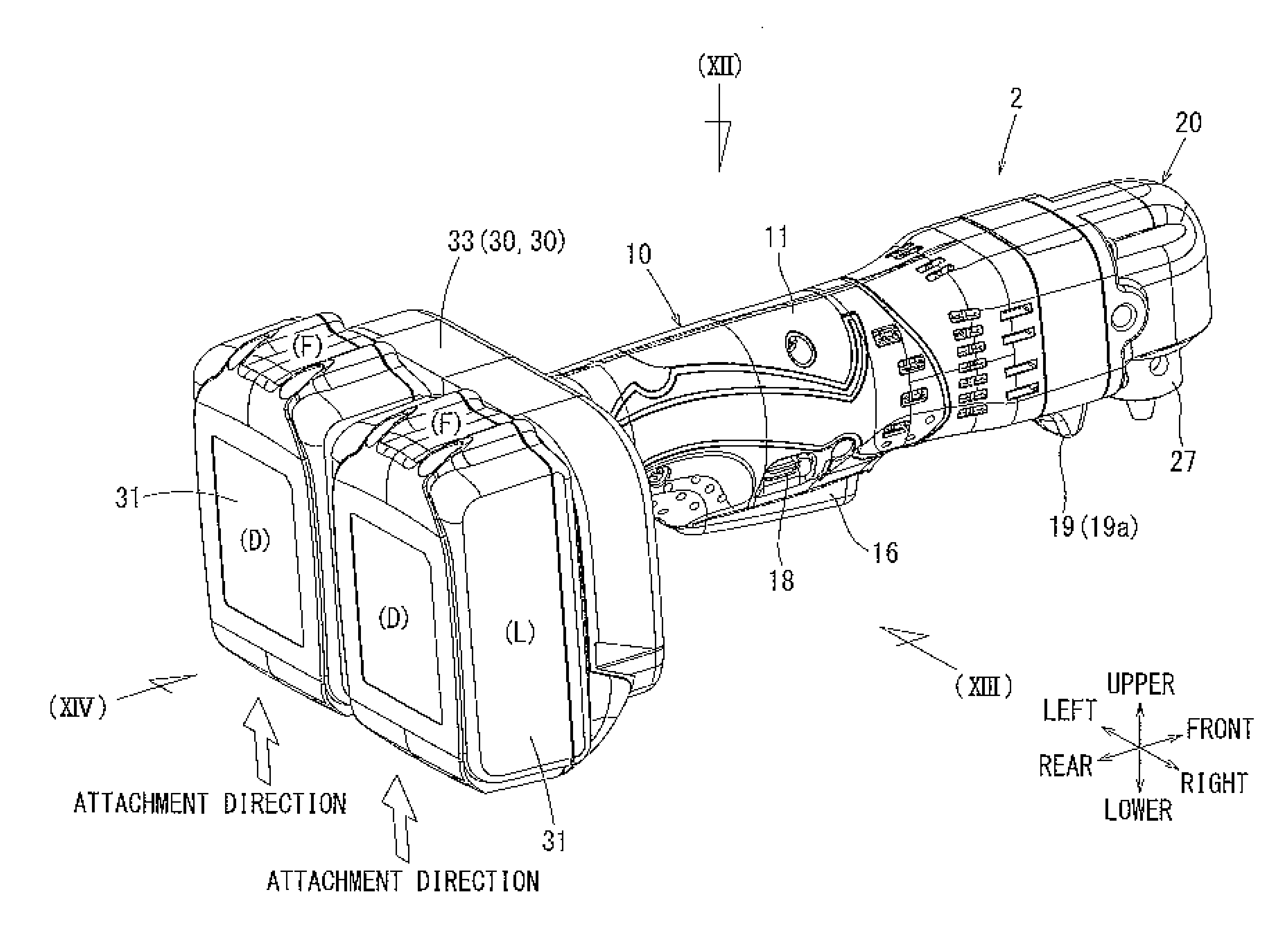
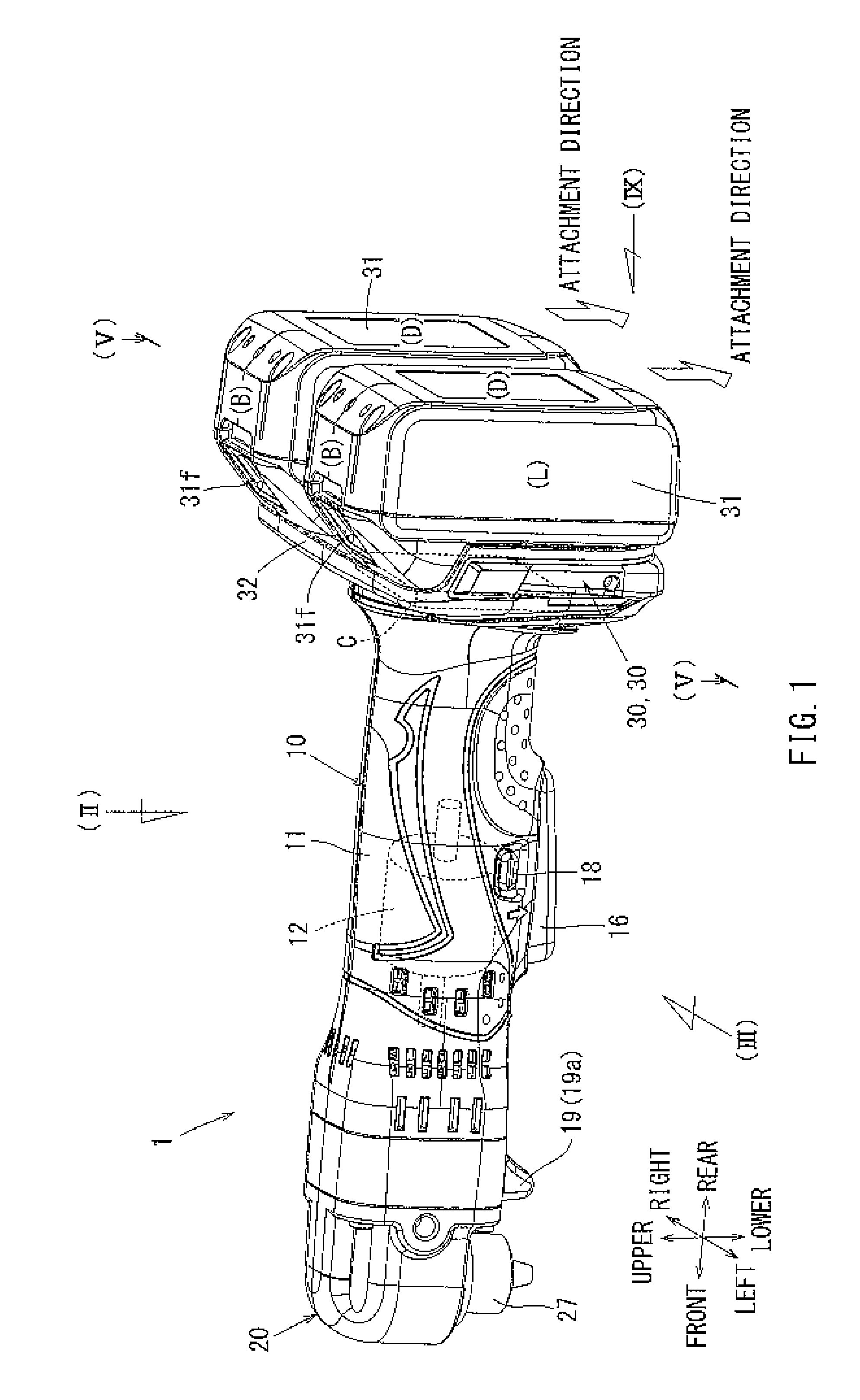
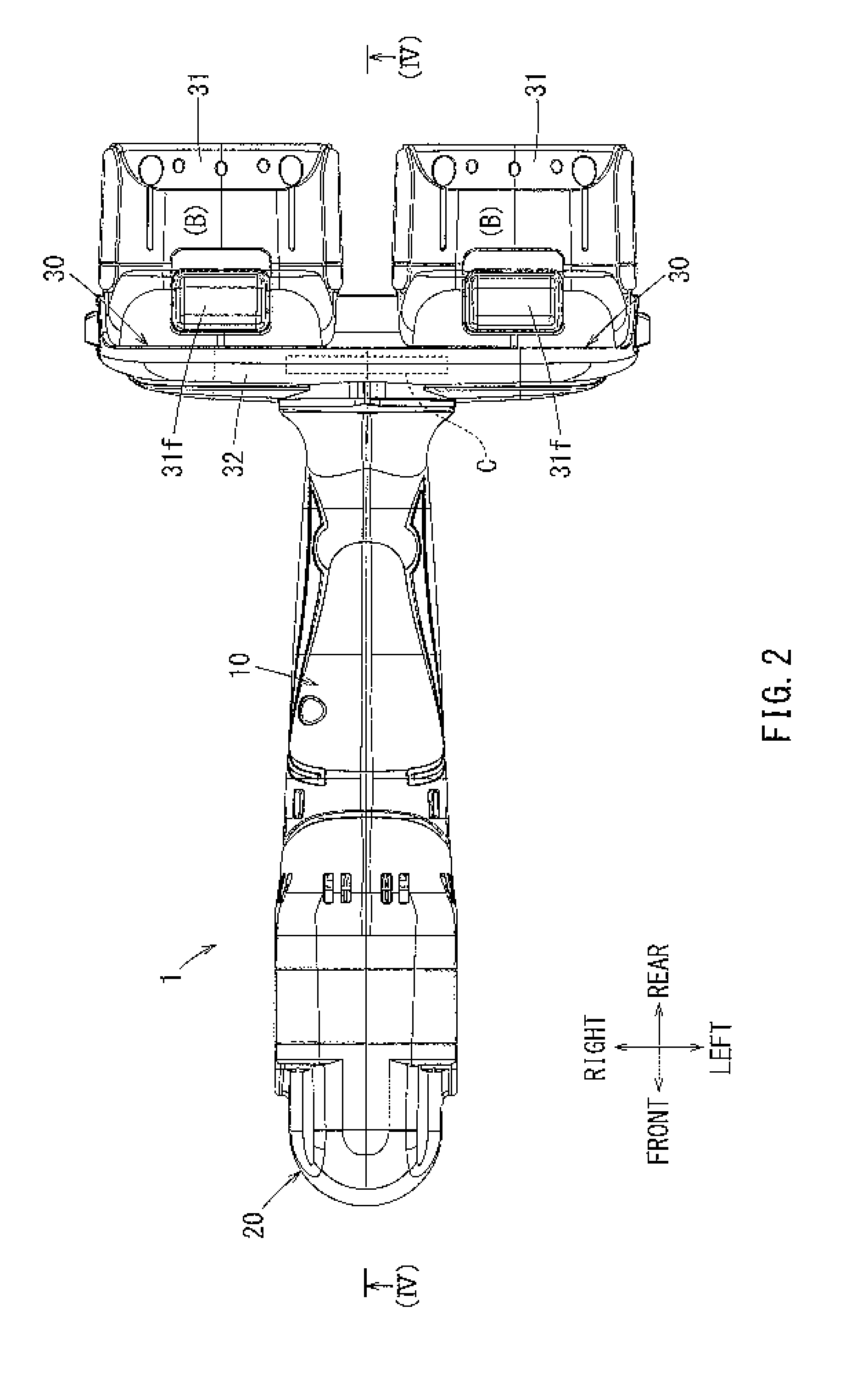
[0139]In the following, a first embodiment of the present invention will be described in further detail with reference to FIGS. 47 through 53. In FIG. 47, reference numeral 110 denotes a disc grinder in correspondence to an electric tool in accordance with the present invention. FIG. 48 is a cut-away view of the disc grinder 110, i.e. where the disc grinder 110 is cut in half across an imaginary axis extending from a front to a rear of the disc grinder 110 as shown by the legend of FIG. 48. FIG. 49 is a plan view (i.e. a diagrammatical view), as seen from below, of the disc grinder shown in FIG. 47. FIG. 50 is a plan view, as seen from behind (i.e., the rear), of the disc grinder shown in FIG. 47. FIG. 51 is a detailed perspective view of a rechargeable battery 180 inserted into and / or attached to a battery attachment portion through, for example, sliding. FIG. 52 is an enlarged plan view of portion (LII) of FIG. 49, illustrating a battery terminal connection portion. FIG. 53 is a c...
second embodiment
[0163]Next, the second and third embodiments, which may be modifications of the first embodiment described above, will be described in further detail with reference to FIGS. 54 through 59. In the second and third embodiments, only the arrangement of the battery attachment portions 160 Differs from that of the disc grinder 110 of the first embodiment. Thus, portions of the disc grinder 110 which are formed substantially in the same manner as in the first embodiment are indicated by like reference numerals in the drawings, and a description thereof will be omitted.
[0164]First, a disc grinder 110A according to the second embodiment will be described. FIG. 54 illustrates a side view of the disc grinder 110A of the second embodiment. FIG. 55 is a plan view, as seen from below, of the disc grinder 110A shown in FIG. 54. FIG. 56 is a plan view, as seen from behind, of the disc grinder 110A shown in FIG. 54. As shown in FIGS. 54 through 56, the battery attachment portions 160 A of the secon...
third embodiment
[0171]Next, a disc grinder 110B in accordance with the third embodiment will be described in further detail. FIG. 57 is a side view illustrating the disc grinder 110B of the third embodiment. FIG. 58 is a plan view, as seen from below, of the disc grinder 110B shown in FIG. 57. FIG. 59 is a plan view, as seen from behind, of the disc grinder 110B shown in FIG. 57. As shown in FIGS. 11 through 13, the battery attachment portions 160B of the third embodiment may also be arranged on the lower connecting portion 116 of the grip housing 112, the same as the battery attachment portions 160 of the first embodiment.
[0172]In further detail, a first battery attachment portion 160Ba and a second battery attachment portions 160Bb may be arranged in parallel and be deviated in right-to-left direction with respect to the lower connecting portion 116. Nevertheless, the first battery attachment portion 160Ba and the second battery attachment portion 160Bb may be arranged such that the connection te...
PUM
 Abstract
Description
Claims
Application Information
 - R&D
- Intellectual Property
- Life Sciences
- Materials
- Tech Scout
- Unparalleled Data Quality
- Higher Quality Content
- 60% Fewer Hallucinations
Browse by: Latest US Patents, China's latest patents, Technical Efficacy Thesaurus, Application Domain, Technology Topic, Popular Technical Reports.
© 2025 PatSnap. All rights reserved.Legal|Privacy policy|Modern Slavery Act Transparency Statement|Sitemap|About US| Contact US: help@patsnap.com


