
No-welding type battery pack using forced-inserting type rivet

a technology of rivets and battery packs, applied in the field of no-welding type battery packs, can solve the problems of low safety of lithium secondary batteries, and combustible materials, and achieve the effects of reducing the manufacturing cost reducing the manufacturing time of lithium secondary batteries, and simplifying the assembly process of lithium secondary batteries

Active Publication Date: 2011-07-12
LG ENERGY SOLUTION LTD
View PDF9 Cites 6 Cited by
  • Summary
  • Abstract
  • Description
  • Claims
  • Application Information

AI Technical Summary

Benefits of technology

The present invention provides a cap assembly for a battery pack that simplifies the assembly process and reduces manufacturing time and costs. The cap assembly includes a base plate, a PCM, and a top cap, all of which are electrically connected and mechanically coupled using rivets. The rivets are inserted through the base plate and PCM, and the top cap covers the PCM. The cap assembly is designed to automate the assembly process and improve the structural stability of the battery pack. The technical effects of the invention include reducing the manufacturing costs of the battery pack, simplifying the assembly process, and improving the structural stability of the battery pack.

Problems solved by technology

However, various combustible materials are contained in the lithium secondary battery.
As a result, there is a possibility of danger in that the lithium secondary battery can be heated or explode due to overcharge, overcurrent, or any other external physical impacts.
In other words, the lithium secondary battery has low safety.
As a result, a possibility of defect is high.
Furthermore, the addition of the welding or soldering processes increases the manufacturing costs of the battery pack.

Method used


Image

  • No-welding type battery pack using forced-inserting type rivet
  • No-welding type battery pack using forced-inserting type rivet
  • No-welding type battery pack using forced-inserting type rivet

Examples


Embodiment Construction

[0031]Now, preferred embodiments of the present invention will be described in detail with reference to the accompanying drawings. It should be noted, however, that the scope of the present invention is not limited by the illustrated embodiments.

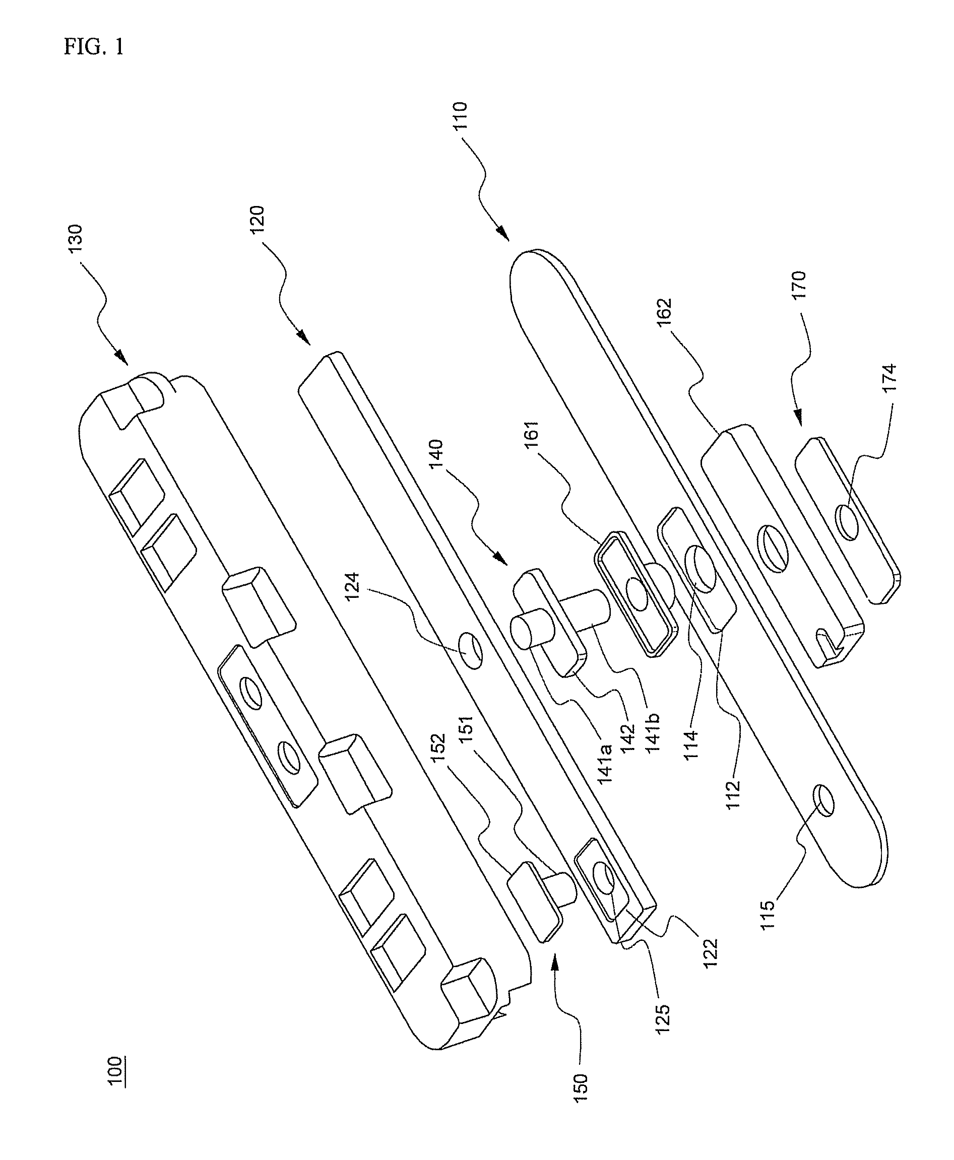
[0032]FIG. 1 is an exploded perspective view illustrating a cap assembly according to a first preferred embodiment of the present invention.

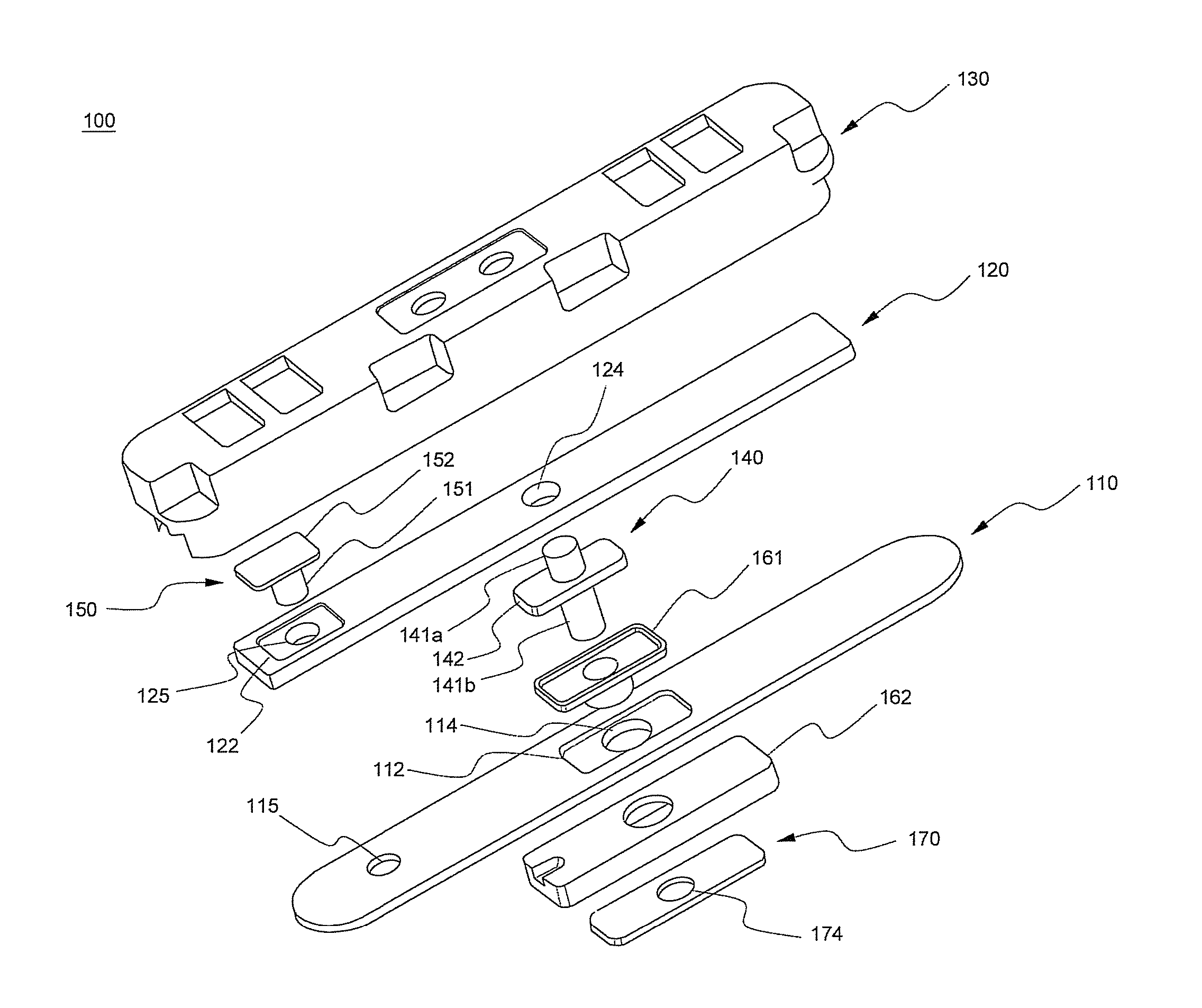
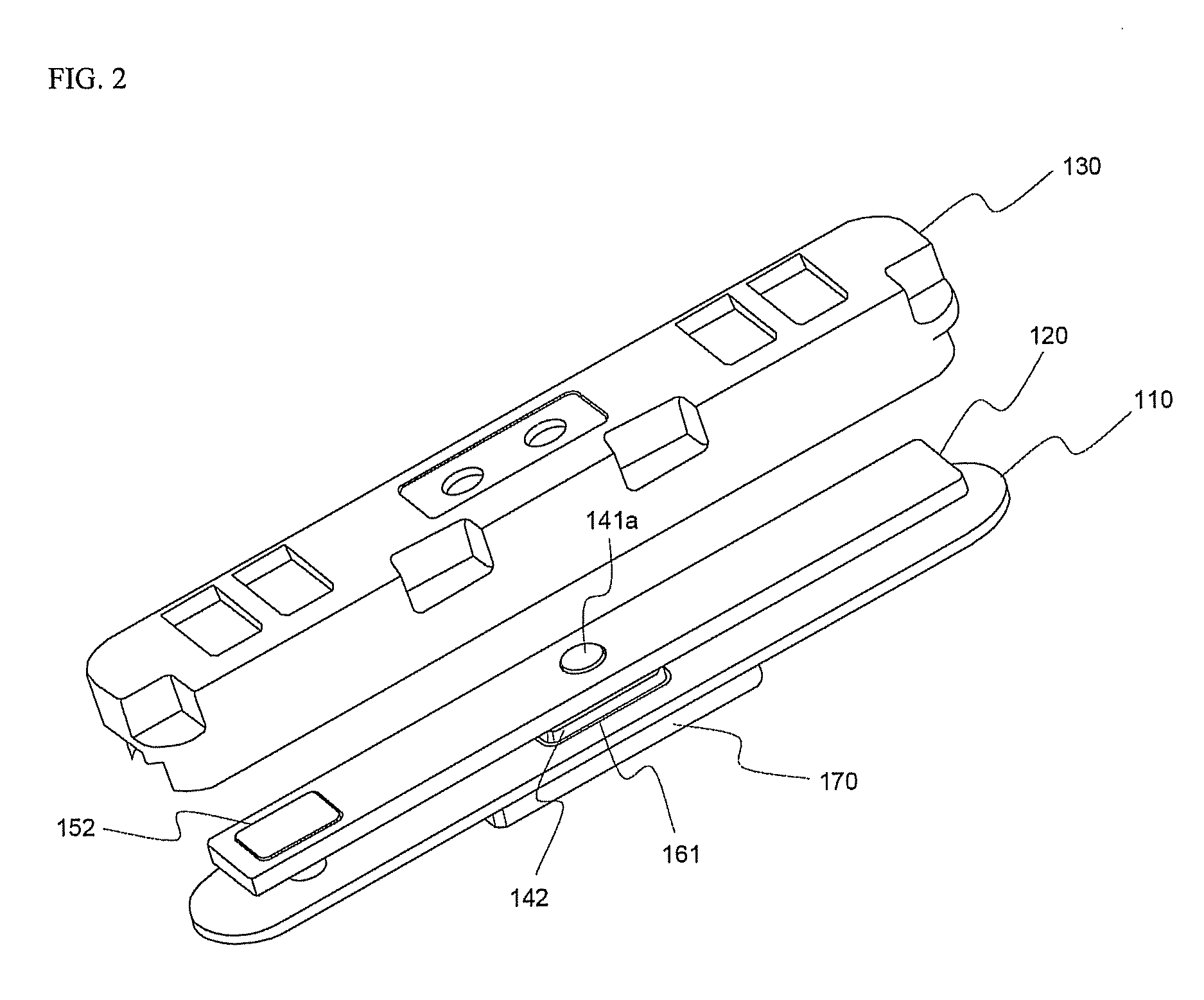
[0033]Referring to FIG. 1, the cap assembly 100 includes a base plate 110 mounted to an open upper end of a battery case (not shown), a protection circuit module (PCM) 120 mounted on the base plate 110, and a top cap 130 coupled to the upper end of the battery case while the top cap 130 covers the PCM 120. The top cap 130 is made of an insulative material.

[0034]The base plate 110 and the PCM 120 are provided in the middles thereof with through-holes 114 and 124, respectively, through which a rivet 140 is inserted. The rivet 140 is connected to an anode of a battery. The base plate 110 and the PCM 120 are...


PUM

PropertyMeasurementUnit
mechanicalaaaaaaaaaa
thicknessaaaaaaaaaa
conductiveaaaaaaaaaa

Abstract

Disclosed herein is a no-welding type battery pack using one or more forced-inserting type rivets. A cap assembly includes a base plate mounted to an open upper end of a battery case, a protection circuit module (PCM) mounted on the base plate, and a top cap coupled to the upper end of the battery case while the top cap covers the PCM. The top cap is made of an insulative material. The electrical connection and the mechanical coupling between the PCM and the base plate are accomplished by one or more forced-inserting type rivets. The cap assembly is included the battery pack. The no-welding type battery pack using the one or more forced-inserting type rivets is manufactured without welding or soldering requiring an excessive amount of time and skilled technique during the electrical connection between the battery cell and the PCM. As a result, the assembly process of the battery pack is simplified, and therefore, the manufacturing time of the battery pack is reduced. Consequently, the manufacturing costs of the battery pack are decreased, the automation of the assembly process is accomplished, and the structural stability of the battery pack is improved.

Description

FIELD OF THE INVENTION[0001]The present invention relates to a no-welding type battery pack using one or more forced-inserting type rivets, and, more particularly, to a cap assembly including a base plate mounted to an open upper end of a battery case, a protection circuit module (PCM) mounted on the base plate, and a top cap coupled to the upper end of the battery case while the top cap covers the PCM, the top cap being made of an insulative material, wherein the electrical connection and the mechanical coupling between the PCM and the base plate are accomplished by one or more forced-inserting type rivets, and a battery pack including the same.BACKGROUND OF THE INVENTION[0002]As mobile devices have been increasingly developed, and the demand of such mobile devices has increased, the demand of secondary batteries has also sharply increased. One of the secondary batteries is a lithium secondary battery having high energy density, high operation voltage, and excellent storage and ser...

Claims


Application Information

Patent Timeline
Patent Type & Authority Patents(United States)
IPC IPC(8): H01M2/34H01M2/04H01M50/147H01M50/183H01M50/528H01M50/586
CPCH01M2/0404H01M2/0473H01M2/22H01M2/34H01M2/08H01M10/052Y02E60/10H01M50/147H01M50/15H01M50/183H01M50/528Y02P70/50H01M50/586
Inventor KIM, JUNG-HWANSONG, SUKJINMOON, KI EOBJUNG, SOONKWANGMOON, JO
Owner LG ENERGY SOLUTION LTD
Learn More