Blade mechanism for a plant material trimming device

a cutting device and blade mechanism technology, applied in the direction of cutting tools, metal working devices, cutters, etc., can solve the problems of time-consuming and labor-intensive cleaning of plant trimming devices

a cutting device and blade mechanism technology, applied in the direction of cutting tools, metal working devices, cutters, etc., can solve the problems of time-consuming and labor-intensive cleaning of plant trimming devices

US9636838B2Active Publication Date: 2017-05-02KEIRTON

Image

  • Blade mechanism for a plant material trimming device
  • Blade mechanism for a plant material trimming device
  • Blade mechanism for a plant material trimming device

Examples


Embodiment Construction

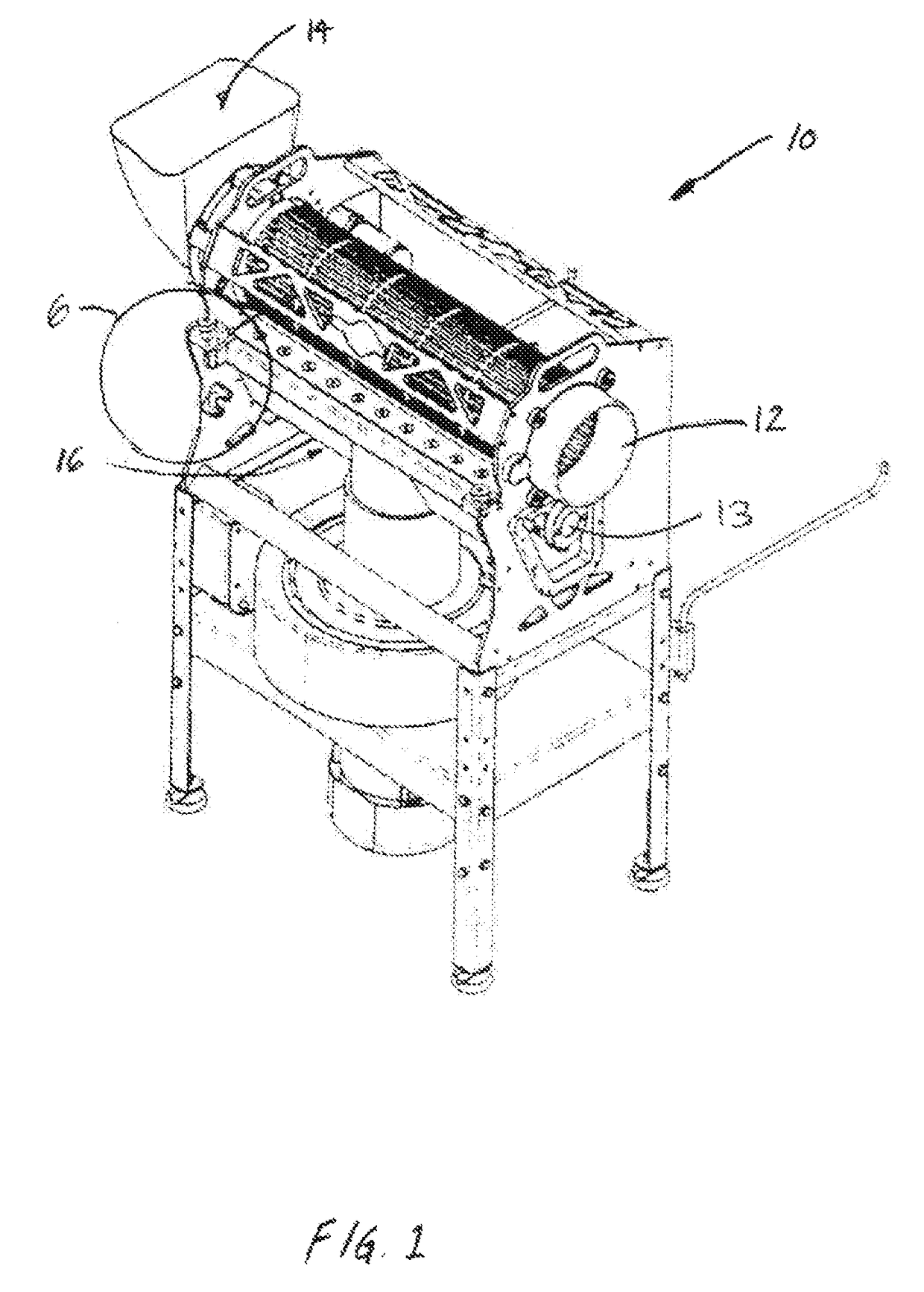
[0019]Referring to FIG. 1, a plant material trimming device 10 is depicted. The device 10 includes a tumbler 12, a rotatable reel 13 with helical blades 15 and a bed bar with a straight blade residing inside of the device. Plant material that requires trimming is inserted into a hopper 14 which then feeds the plant material into the tumbler 12. A blade mechanism 16 is pivotably attached to the end walls 11 and is situated inside of the device 10 adjacent the tumbler 12 and the rotatable reel 13 with helical blades 15. As the plant material is tumbled in the tumbler 12, the blade mechanism 16 in cooperation with the helical blades 15 cuts the plant material in a scissor-like fashion as the plant material is exposed between the blade mechanism and tumbler walls.

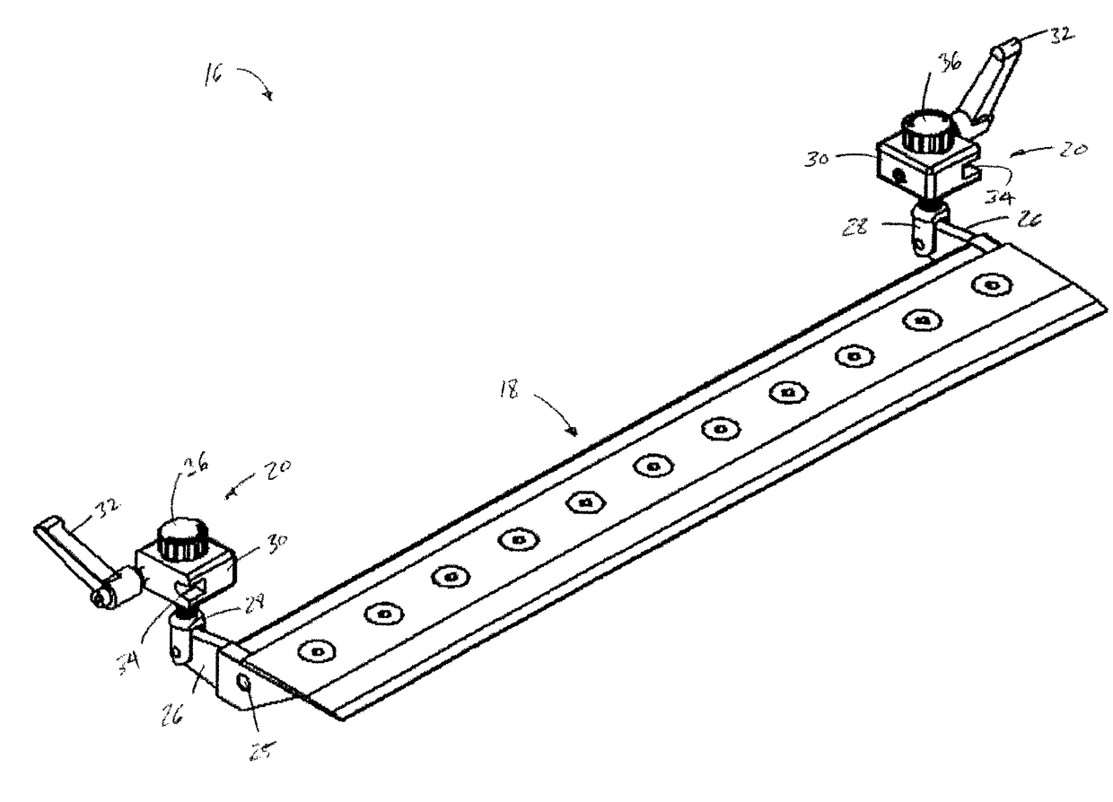
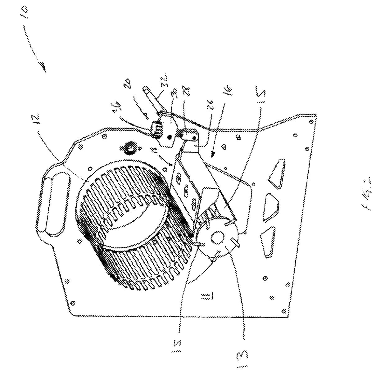
[0020]Referring to FIGS. 2 and 3 the blade mechanism 16 includes a blade bar 18 and is pivotably connectable to a wall 11 of the plant material trimming device 10 through pivot holes 25 and a hand-operated means for adjusting, ...


PUM


Abstract

A plant material trimming device includes two end walls supporting a rotatable perforated tumbler, a rotatable reel with helical blades, and a blade mechanism pivotably connected to the end walls of the device. The blade mechanism includes: (i) a blade bar configured to cut plant material in cooperation with the helical blades when the device is in operation; (ii) a first arm operatively associated with the blade bar; and (iii) a second arm pivotably connected to the first arm such that the second arm can pivot downward when the blade mechanism is unlocked. A tightening block may be threadedly connected to the second arm and connectable to one of the two end walls. The tightening block may be configured for adjusting the pitch of the blade bar relative to the helical blades when the blade mechanism is locked to the end walls.

Description

COPYRIGHT NOTICE[0001]This patent document contains material which is subject to copyright protection. The copyright owner has no objection to the facsimile reproduction by anyone of this patent document as it appears in the Patent and Trademark Office patent file or records, but otherwise reserves all copyright rights whatsoever.FIELD OF THE INVENTION[0002]The invention relates to the field of plant trimming devices, and in particular, to a blade mechanism for a plant material trimming device.BACKGROUND OF THE INVENTION[0003]Plant trimming devices, which comprise a rotatable perforated tumbler, a cutting mechanism that comprises a rotatable reel with helical blades, and a bed bar with a straight blade, have been in operation for some time. Examples are provided by U.S. Pat. No. 9,161,566 (Hall) and US Patent Application Number 2014 / 0196587 (Beyerlein & Luo). Another example of a plant trimming device comprising a tumbler and cutting reel is described in U.S. Pat. No. 8,757,524 (Mos...

Claims


Application Information

Patent Timeline
02 May 2017
Publication
US9636838B2
IPC
B26D1/40; B26D7/26; A01G3/00
CPC
B26D1/40; B26D7/2614; A01G3/002
Inventors
EVANS, JAY; MCKELLAR, AARON