
Phugoid peaks trajectory for hypersonic glide vehicles

Active Publication Date: 2017-05-02
GOVERNMENT OF THE UNITED STATES AS REPRESENTED BY THE SEC OF THE AIR FORCE
View PDF4 Cites 13 Cited by
  • Summary
  • Abstract
  • Description
  • Claims
  • Application Information

AI Technical Summary

Benefits of technology

The present invention proposes a new glide trajectory that reduces heat loads while maintaining range. This trajectory uses a phugoid peaks design, which results in a simpler and lighter weight design for thermal protection and internal thermal management systems. This reduces development time, production time and costs, and mitigates design risks. Overall, this new trajectory is an effective solution to address challenges associated with conventional maximum lift to drag trajectories.

Problems solved by technology

Hypersonic glide vehicles can achieve their significant efficiencies within the limits of modern materials, but not without large amounts of heat shielding, significantly reducing available passenger and cargo space and weight carrying capacity, and often not without additional mechanically complex heat removing systems.
Such heat removing systems typically attempt to radiate the heat away from the vehicle and delay heat from entering the vehicle.
Reducing glide speed, however, reduces range and, more importantly, removes a primary reason for a hypersonic glide vehicle, time to destination.
Maximum L / D glide trajectories result, however, in higher speeds and higher instantaneous heat rates.
A modified glide trajectory with constant speed limits the maximum speed, but reduces range.
Increasing altitude helps preserve range, but also increases drag (and resulting integrated heat load) and time to destination.
A particular problem with such tradeoffs is integrated heat load, the total heat load over time.
In that paper and associated presentation, the authors explained that a phugoid trajectory maximizes range, is similar to a maximum L / D trajectory, but is undesirable for a variety of reasons, primary heat loading.

Method used


Image

  • Phugoid peaks trajectory for hypersonic glide vehicles
  • Phugoid peaks trajectory for hypersonic glide vehicles
  • Phugoid peaks trajectory for hypersonic glide vehicles

Examples


example embodiment

[0045]The teachings of the present invention can be implemented by use of such industry standard trajectory tools as POST (Program to Optimize Simulated Trajectories II), originally written Lockheed Martin Astronautics and NASA-Langley; and, OTIS (Optimal Trajectories by Implicit Simulation), originally written by The Boeing Corporation with NASA-Glenn Research Center. The vehicle inputs to the trajectory tool are vehicle weight, aerodynamic reference area and wing loading.

[0046]A hypersonic trajectory starts at the same specific energy state and ends at the same specific energy state as defined by a reference altitude and velocity. Specific energy is the sum of potential and kinetic energy. POST utilizes the specific energy equation used for orbital mechanics shown in Eq. (1). This formula for energy is zero for a circular orbit. For simplicity, aerodynamics are assumed to be constant over all Mach numbers and trimmed.

[0047]e=VI22-μrI,Eq.⁢(1)[0048]where[0049]μ=1.41×1016 ft3 / sec2 (E...


PUM


Abstract

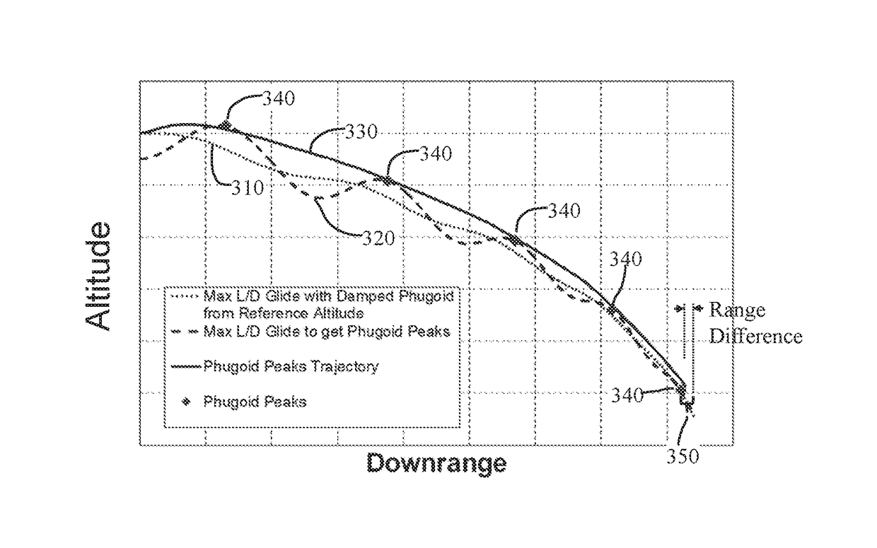
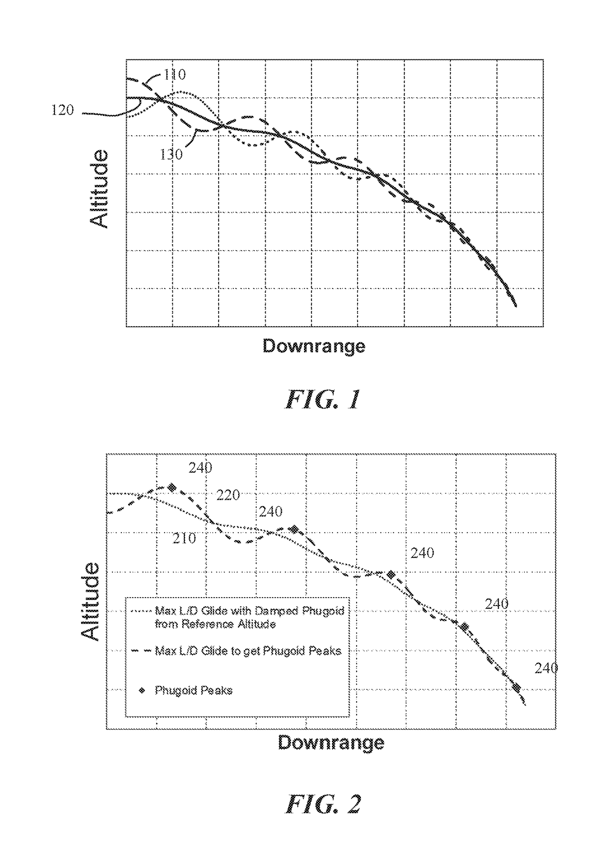
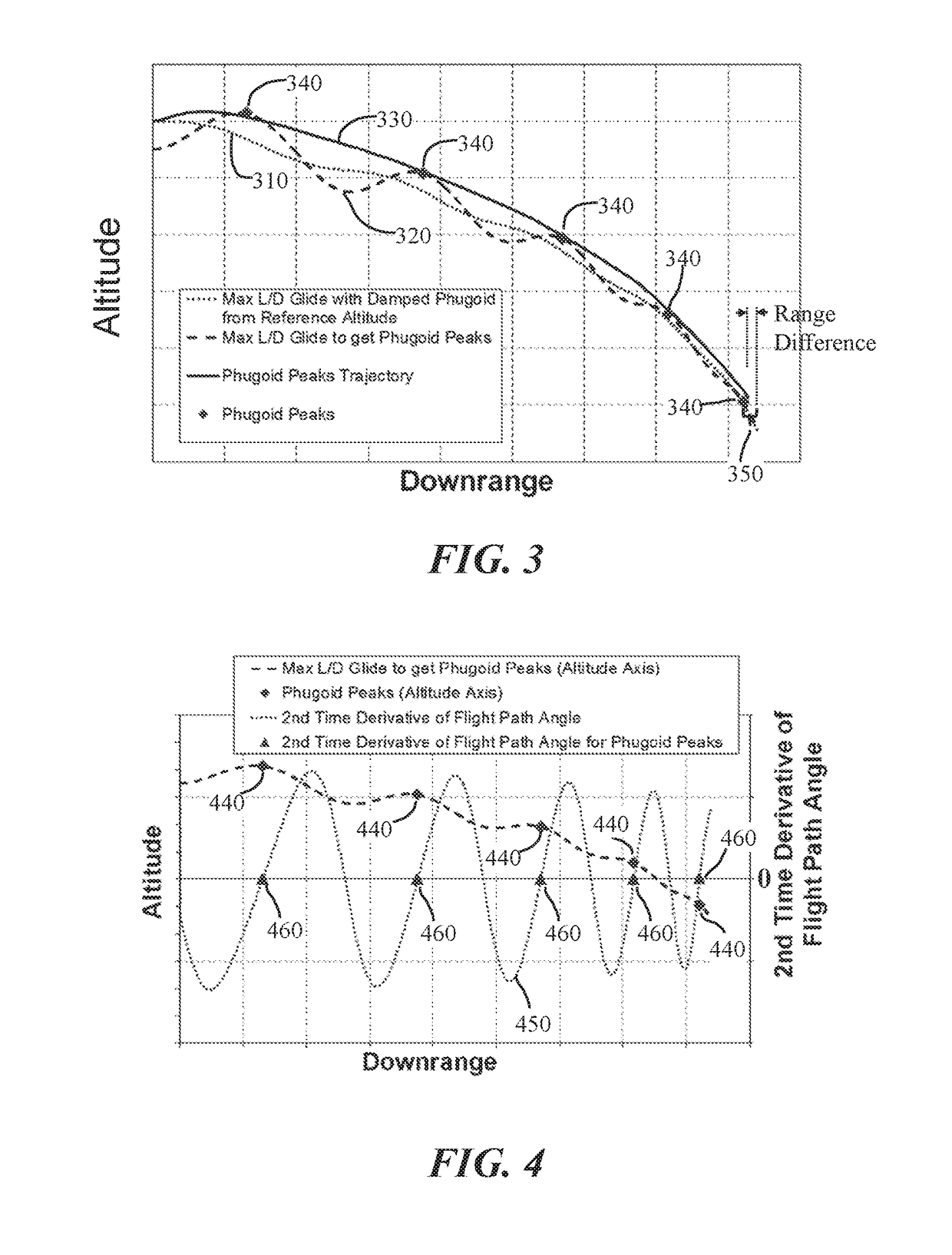
A new apparatus and method for determining trajectories for hypersonic glide vehicles significantly reduces integrated, or total, heat load, with little reduction in time to distance and maximum range. The new approach identifies a trajectory having large phugoid oscillations and plotting a glide trajectory along the peaks of the phugoid oscillations. The glide trajectory is determined by calculating a first altitude that results in a maximum lift to drag ratio trajectory having damped or small phugoid oscillations, then calculating a different altitude that results in larger phugoid oscillations, and higher phugoid peaks, and finally plotting a trajectory from the first altitude that follows the peaks of the higher phugoid oscillation trajectory. The thus calculated trajectory can be input into a glide vehicle guidance system for controlling the trajectory of the glide vehicle from a point where it reaches the first altitude.

Description

RIGHTS OF THE GOVERNMENT[0001]The invention described herein may be manufactured and used by or for the Government of the United States for all governmental purposes without the payment of any royalty.BACKGROUND OF THE INVENTION[0002]The present invention relates generally to hypersonic glide vehicles, and more specifically to glide trajectories that reduce heat loading from aerodynamic heating, primarily the total heat load over an entire glide trajectory, called integrated heat load, with little loss of range.[0003]Hypersonic glide vehicles are launched to a high altitude on a rocket or other boost vehicle and then glide to their destinations at hypersonic speeds.[0004]Future commercial hypersonic glide vehicles may provide travel times under an hour from London to New York, Los Angeles or Beijing; from New York to Beijing; and, from Los Angeles to Beijing or Sydney; and; under ninety minutes from London or New York to Sydney.[0005]Proposed future commercial hypersonic glide vehic...

Claims


Application Information

Patent Timeline
IPC IPC(8): G05D1/00B64C30/00G01C23/00G05D1/06B64C31/00B64G1/24
CPCG05D1/0607G01C23/005B64G1/24B64G1/242B64C31/00B64C30/00Y02T50/80B64G2001/245Y02T50/84B64G1/244B64G1/245
Inventor HELLMAN, BARRY M.
Owner GOVERNMENT OF THE UNITED STATES AS REPRESENTED BY THE SEC OF THE AIR FORCE
Learn More