
Blood vessel diameter measurement device

a measurement device and blood vessel technology, applied in the field of blood vessel diameter measurement devices, can solve the problems of inaccurate inability of ultrasonic elements to accurately receive the reflected ultrasonic waves, and decrease in the intensity of the ultrasonic waves reflected by the wall surface of the blood vessel, etc., to achieve accurate measurement, accurate calculation, and accurate measurement of the diameter of the blood vessel

Active Publication Date: 2017-05-09
SEIKO EPSON CORP
View PDF10 Cites 0 Cited by
  • Summary
  • Abstract
  • Description
  • Claims
  • Application Information

AI Technical Summary

Benefits of technology

[0009]An object of the present invention is to provide a blood vessel diameter measurement device whereby the diameter of a blood vessel can be accurately measured.
[0023]According to this aspect, the warning output unit compares the offset amount of the estimated center position of the blood vessel and the center coordinates computed by the outside diameter computation unit and the inside diameter computation unit, and outputs a warning in the case that the offset amount exceeds the threshold value. In this case, by reattaching the probe and performing another measurement, in the same manner as described above, the center coordinates of the blood vessel can be calculated more accurately, and the diameter of the blood vessel can be accurately measured.

Problems solved by technology

Therefore, of the ultrasonic waves transmitted not orthogonally to the wall surface of the blood vessel, the intensity of the ultrasonic waves reflected by the wall surface of the blood vessel decreases, and the ultrasonic elements are unable to accurately receive the reflected ultrasonic waves.
An inaccurate measurement of the diameter of the blood vessel may therefore result.
In cases where the blood vessel wall has a small thickness, or the blood vessel is constricted, it is impossible to distinguish between reflected ultrasonic waves that are reflected by the inside wall or the outside wall, and it may therefore be impossible to accurately compute the diameter of the blood vessel.

Method used


Image

  • Blood vessel diameter measurement device
  • Blood vessel diameter measurement device
  • Blood vessel diameter measurement device

Examples


embodiment

Modifications of Embodiment

[0135]The present invention is not limited to the embodiment described above, and modifications, improvements, and the like in a range in which the objects of the present invention can be achieved are included within the scope of the present invention.

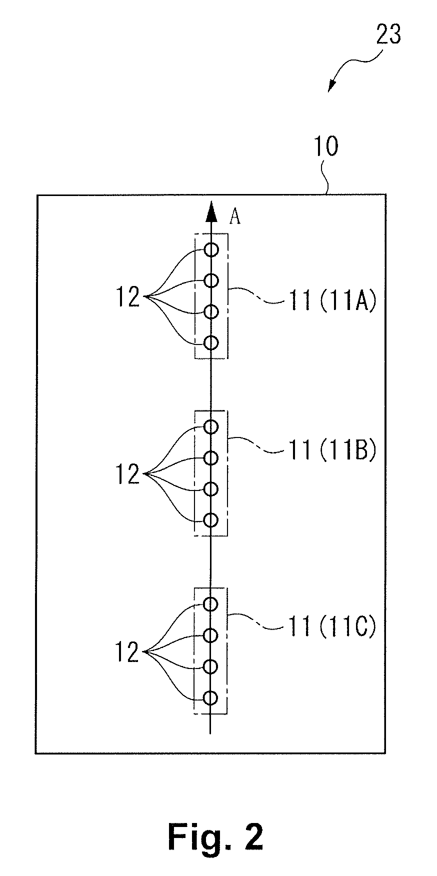
[0136]In the embodiment described above, the center position of the blood vessel is estimated based on two reflected waves of the ultrasonic waves that are transmitted from two ultrasonic arrays 11, but the center position of the blood vessel may also be estimated based on three reflected waves from the reflected waves of the ultrasonic waves transmitted from three ultrasonic arrays 11. In this case, the center position can be estimated with greater precision than in the case of estimating the center position of the blood vessel by using two ultrasonic arrays 11.

[0137]In the embodiment, described above, a blood vessel diameter measurement device 1 is described which uses three ultrasonic arrays 11, but this c...


PUM


Abstract

A control part includes a transmission angle control unit that controls a transmission angle of ultrasonic waves transmitted from three ultrasonic arrays, a first reflected wave measuring unit that measures a first arrival time of a first reflected wave which is reflected by a blood vessel and is first to arrive at the ultrasonic arrays, a second reflected wave measuring unit that measures a second arrival time of a second reflected wave which arrives at the ultrasonic arrays after a predetermined time from the first arrival time, an outside diameter computation unit that computes an outside diameter of the blood vessel based on the first arrival time of three first reflected waves, and an inside diameter of the blood vessel computation unit that computes an inside diameter based on the second arrival time of three second reflected waves.

Description

CROSS-REFERENCE TO RELATED APPLICATIONS[0001]This application claims priority to Japanese Patent Application No. 2010-234551 filed on Oct. 19, 2010. The entire disclosure of Japanese Patent Application No. 2010-234551 is hereby incorporated herein by reference.BACKGROUND[0002]Technical Field[0003]The present invention relates to a blood vessel diameter measurement device for measuring the diameter of a blood vessel in a living body by using ultrasonic waves.[0004]Related Art[0005]A conventional measurement device is known which measures the diameter of a blood vessel in a living body by using ultrasonic waves (see Japanese Patent No. 4441664, for example).[0006]In this measurement device according to Japanese Patent No. 4441664, an ultrasonic probe is provided which is provided with a first array and a second array in a direction which intersects with the axial direction of a blood vessel. Each array has a plurality of ultrasonic elements. In each array, the plurality of ultrasonic ...

Claims


Application Information

Patent Timeline
Patent Type & Authority Patents(United States)
IPC IPC(8): A61B8/06G01B17/00A61B8/00A61B8/08G01B17/02A61B5/00
CPCA61B8/0891A61B8/4444G01B17/00G01B17/02A61B5/489
Inventor NAKAZAWA, YUSUKE
Owner SEIKO EPSON CORP
Learn More