Chopper output stage for arc welder power source

a technology of arc welding and output stage, which is applied in the direction of electric variable regulation, instruments, manufacturing tools, etc., can solve the problems of relatively low current provided by individual power circuits, and achieve the effect of significantly degrading system efficiency, facilitating basic understanding, and increasing the bandwidth of output stag

Active Publication Date: 2017-05-09
LINCOLN GLOBAL INC
View PDF207 Cites 7 Cited by
  • Summary
  • Abstract
  • Description
  • Claims
  • Application Information

AI Technical Summary

Benefits of technology

[0009]A summary of one or more aspects of the invention is now presented in order to facilitate a basic understanding thereof, wherein this summary is not an extensive overview of the invention, and is intended neither to identify certain elements of the invention, nor to delineate the scope of the invention. Rather, the primary purpose of the summary is to present some concepts of the invention in a simplified form prior to the more detailed description that is presented hereinafter. The present invention relates to improved welder power sources in which an interleaved multiphase switching converter is employed as a regulated final stage in a power source of the novel concept with an intermediate unregulated DC to DC converter. The interleaved multiphase converter provides regulated signals suitable for welding, i.e., also plasma cutting, and can be operated at switching frequencies impractical in equivalent single phase converters, whereby the advantages of higher output stage bandwidth can be achieved without significantly degrading system efficiency and without unduly adding to the system cost. In this regard, the use of multiple phases or power circuits in the high speed output chopper results in reduced ripple current levels, whereby the size and values of output chokes or inductors can be reduced. This inductor size reduction facilitates the use of board mounted chokes instead of larger chokes found in single phase converters, and the reduced inductance values improves the dynamic transient response of the output stage. Moreover, the individual parallel power circuits can be designed for a given maximum current rating with the number of power circuits in a given power source design being determined by the desired converter current output, whereby different welding or plasma cutting systems can be designed using different numbers of modular chopper power circuits. Furthermore, since the currents provided by the individual power circuits are relatively low, high efficiency and low component current stresses can be achieved, while providing potentially unlimited bandwidth for advanced welding techniques.
[0010]In accordance with one or more aspects of the invention, the novel three stage arc welding or cutting power source is provided with a third stage including an interleaved multiphase switching converter. In this manner, the first stage receives an AC input signal and provides a first DC output signal and the second stage is an unregulated converter coupled to receive the first DC output signal and convert the first DC output signal into a second DC output signal. The third stage of the power source receives the second DC output signal, and includes a plurality of converter power circuits that convert the second DC output signal to provide a signal suitable for a welding or cutting process. The third stage converter power circuits are connected in parallel between the welding and the novel unregulated second stage, and are operated out of phase with respect to one another so as to minimize ripple current levels, whereby the overall ripple current rating of the third stage converter is less than that of the individual converter power circuits. The individual converter power circuits can be buck or other type converters, where the inductors of the converter power circuits may be integrated onto a single core in coupled or uncoupled fashion for system size and cost reduction, and two or more of the power circuits can be operated with temporal overlap. In addition, the converter power circuits can be designed for a given voltage range, where the parallel connection of N power circuits provides the third stage with a converter maximum current rating that is about N times the maximum current rating of the individual converter power circuits. This allows construction of welding power sources operable at virtually any current amperage where the individual converter power circuit modules are designed for operation at typical welding voltage levels, wherein the welder output voltage is essentially unrelated to the number of output stage converter power circuits.

Problems solved by technology

Furthermore, since the currents provided by the individual power circuits are relatively low, high efficiency and low component current stresses can be achieved, while providing potentially unlimited bandwidth for advanced welding techniques.

Method used


Image

  • Chopper output stage for arc welder power source
  • Chopper output stage for arc welder power source
  • Chopper output stage for arc welder power source

Examples


Embodiment Construction

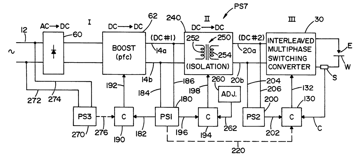
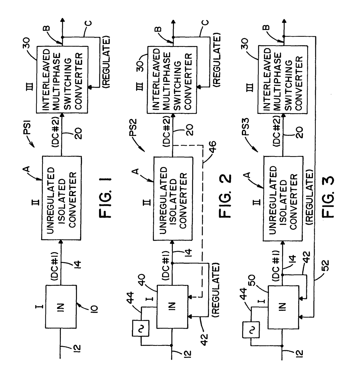
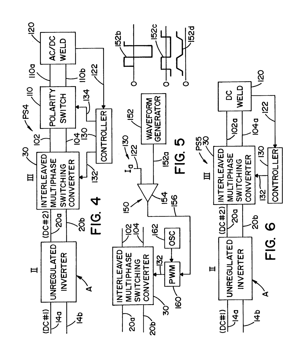
[0025]One or more embodiments or implementations of the present invention are hereinafter described in conjunction with the drawings, wherein like reference numerals are used to refer to like elements throughout and wherein the illustrated structures are not necessarily drawn to scale. Certain aspects of the invention relate to three stage power sources for use in creating output signals suitable for welding or plasma cutting operations, collectively referred to hereinafter as welding power sources, wherein the concept of electric arc welding also encompasses the related technology of plasma arc cutting. An input stage is provided for converting an AC signal into a first DC output signal, which preferably has a fixed voltage level, and an unregulated second stage is also provided, which may include isolation components, and which provides a second DC output signal. Importantly, the third power source stage is constructed as an interleaved multiphase converter which converts the seco...


PUM

PropertyMeasurementUnit
switching frequencyaaaaaaaaaa
voltageaaaaaaaaaa

Abstract

Power sources are disclosed for electric arc welding or cutting processes, in which an interleaved multiphase switching converter is provided with a plurality of converter power circuits to convert a DC signal to a regulated signal suitable for welding.

Description

FIELD OF THE INVENTION[0001]The present invention relates generally to power sources for welding and plasma cutting equipment, and more particularly to an interleaved multiphase chopper output stage in a three stage power source for welding or cutting systems.INCORPORATION BY REFERENCE[0002]The following patents and patent applications and other documents are hereby incorporated by reference as background information: Calkin U.S. Pat. No. 3,737,755; Fletcher U.S. Pat. No. 3,984,799; Karadsheh U.S. Pat. No. 4,433,370; Ogawa U.S. Pat. No. 4,748,397; Parsley U.S. Pat. No. 5,008,795; Smolenski U.S. Pat. No. 5,019,952; Blankenship U.S. Pat. No. 5,278,390; Thommes U.S. Pat. No. 5,601,741; Baker U.S. Pat. No. 5,864,116; Moriguchi U.S. Pat. No. 5,926,381; Kooken U.S. Pat. No. 5,991,169; Vogel U.S. Pat. No. 5,991,180; Reynolds U.S. Pat. No. 6,051,804; Moriguchi U.S. Pat. No. 6,069,811; Church U.S. Pat. No. 6,177,645; Moriguchi U.S. Pat. No. 6,278,080; Reynolds U.S. Pat. No. 6,300,589; Church...

Claims


Application Information

Patent Timeline
Patent Type & Authority Patents(United States)
IPC IPC(8): B23K9/10H02M1/42H02M3/158H02M5/42H02M3/337H02M1/00
CPCH02M3/1584B23K9/1056H02M1/4225H02M3/337H02M2001/007H02M2001/0064Y02P70/181Y02P70/10H02M1/0064H02M1/007H02M3/33573H02M3/28
Inventor KOOKEN, TODD E.SPEAR, THERESA CHIH-LEI MIAO
Owner LINCOLN GLOBAL INC
Why Eureka
Try Eureka