Digital self-interference residual cancellation

a residual cancellation and digital technology, applied in the field of digital self-interference residual cancellation, can solve problems such as interference with desired reception, leakage of receive band frequency, interference with energy,

Active Publication Date: 2017-05-09
LGS INNOVATIONS
View PDF149 Cites 17 Cited by
  • Summary
  • Abstract
  • Description
  • Claims
  • Application Information

AI Technical Summary

Benefits of technology

[0009]In one aspect, a digital self-interference residual cancellation method adjusts a magnitude of a sampled transmit signal based on compared magnitude and phases associated with tones. The digital self-interference residual cancellation method may follow an analog carrier cancellation stage where the digital self-interference residual cancellation is based on a determination of the channel circuit response used to control an infinite impulse response filter which can compensate using both poles and zeroes.

Problems solved by technology

Interfering energy, which is generated by the transmitter nonlinearities and other noise processes, is leaked into the receive band frequencies where it interferes with desired reception.
The drawback is these components are typically quite large to meet the isolation requirements of modern communications systems.
Multi-band operation of such systems requires complex and limited multiplexer designs or a very large switch network of duplexers.
These duplexers are typically constructed of a metal housing with air-filled internal cavities and are therefore large and heavy.
This further exacerbates the linearity problem due to the difficulties in matching the PA for best linearity versus power over a wide bandwidth.
The continued worldwide adoption of 4G (e.g., Long-Term Evolution—LTE) adds other challenges, both in terms of the proliferation of bands and the increased interference emitted from the power amplifier.
This increased interference requires larger duplexers.
Further 4G operates over wider bands increasing the challenge of self-interference cancellation schema.
The trend for cellular waveforms is an increase in the requirement for transmit-to-receive isolation, which requires more difficult filter requirements.
This can require a large number of filters for a multi-band transceiver.
These problems are exacerbated when the transceiver operates at high power, for example, micro-class and macro-class base stations.
Such frequency division duplex systems cannot operate for existing defined cellular standards or other wireless communication standards that separate transmit and receive energy based on frequency (FDD).
Frequency hopping for security of communications in multi-band systems has been slow and cumbersome, as reconfiguration of a transceiver between bands requires reconfiguration of duplexers and other elements of the system.
Providing security for radio communications via switching bands and operating frequencies during the operation of the system has been slow and cumbersome.
Even more difficult is the operation of transmit and receive operations in different bands which may be separated by changing separation bands.

Method used


Image

  • Digital self-interference residual cancellation
  • Digital self-interference residual cancellation
  • Digital self-interference residual cancellation

Examples


Embodiment Construction

[0044]A detailed description of the illustrative embodiments will be discussed in reference to various figures, embodiments and aspects herein. Although this description provides detailed examples of possible implementations, it should be understood that the details are intended to be examples and thus do not limit the scope of the application.

[0045]Reference in this specification to “one embodiment,”“an embodiment,”“one or more embodiments,”“an aspect” or the like means that a particular feature, structure, or characteristic described in connection with the embodiment is included in at least one embodiment of the disclosure. Moreover, the term “embodiment” in various places in the specification is not necessarily referring to the same embodiment. That is, various features are described which may be exhibited by some embodiments and not by the other.

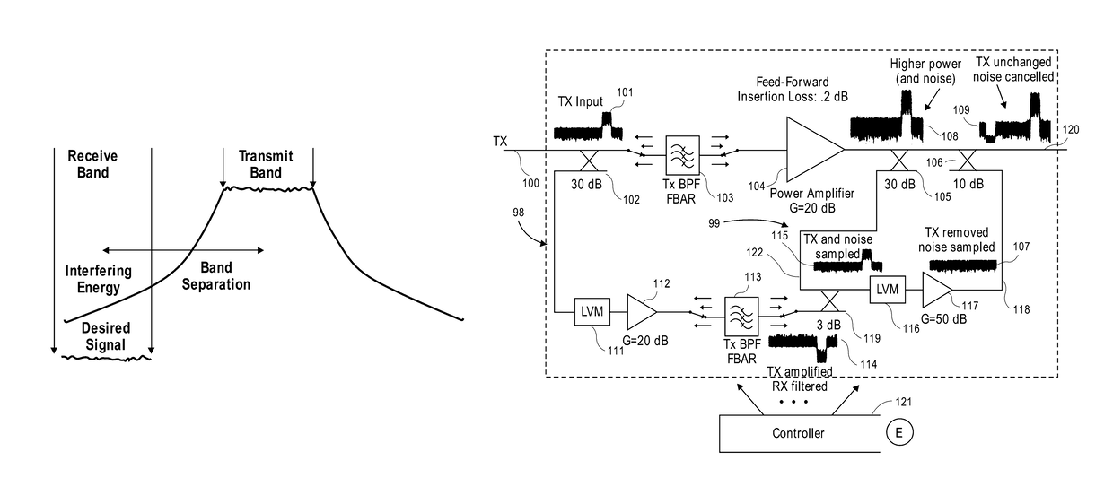
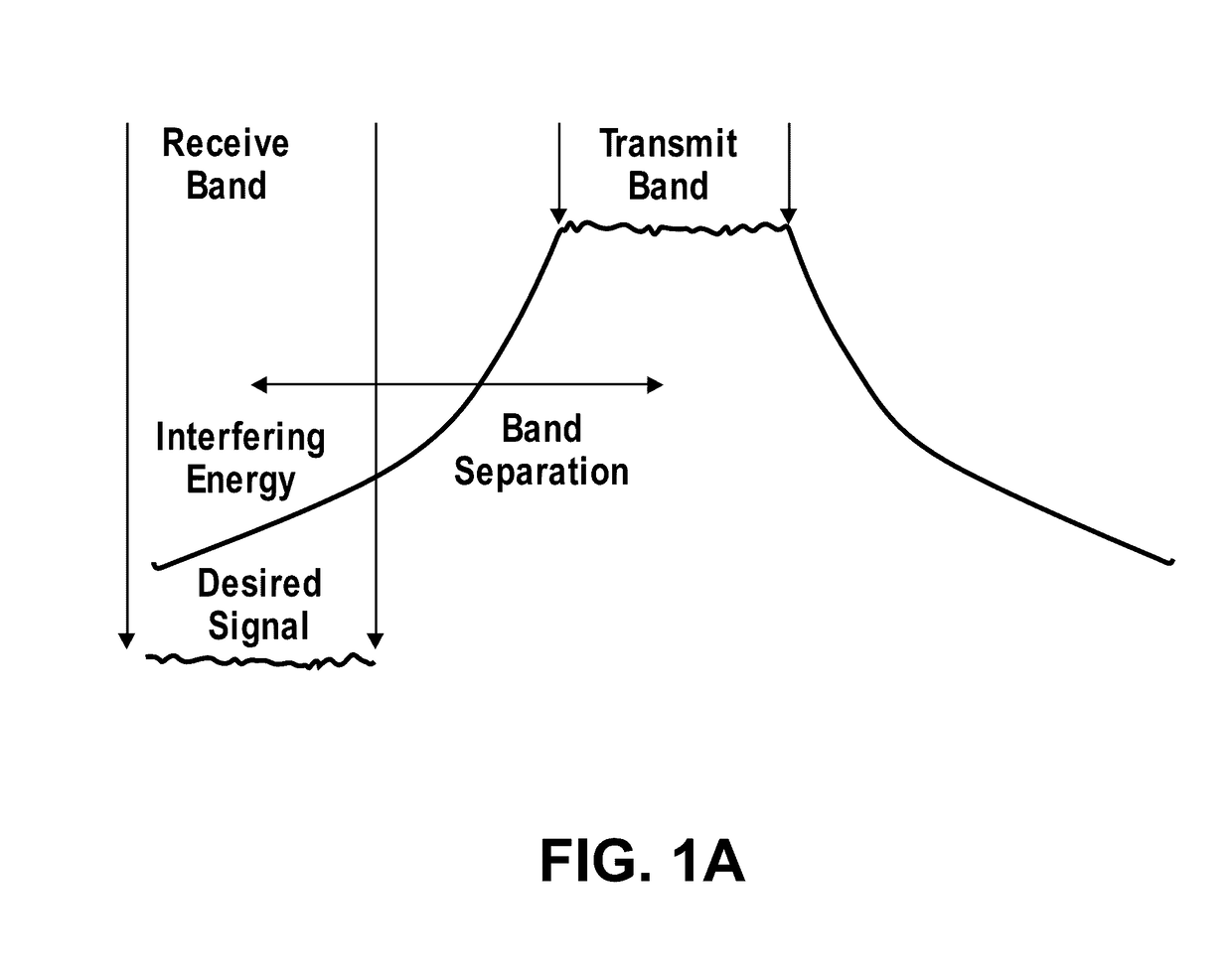
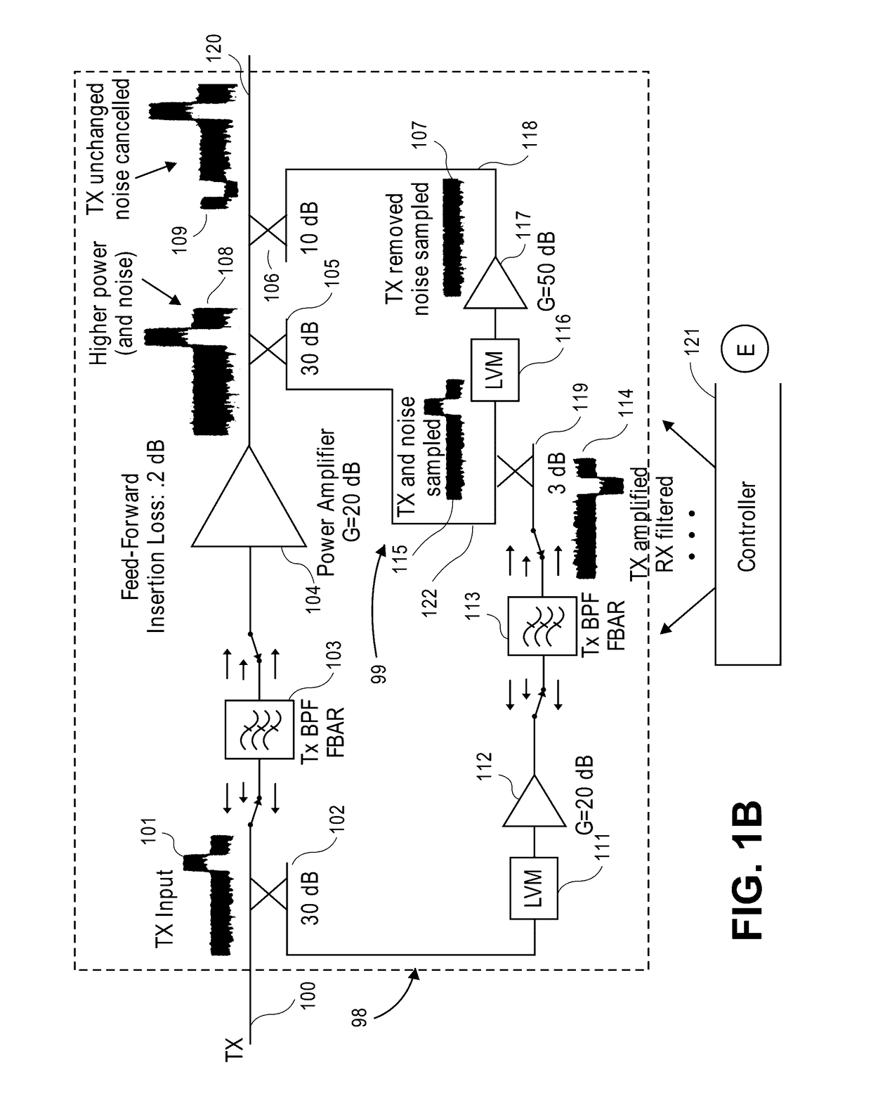
[0046]Generally, many cellular and other communications systems operate in a frequency division duplex manner—simultaneous transmission...


PUM


Abstract

The present application a digital self-interference residual cancellation method that adjusts a magnitude of a sampled transmit signal based on compared magnitude and phases associated with tones. The digital self-interference residual cancellation method may follow an analog carrier cancellation stage where the digital self-interference residual cancellation is based on a determination of the channel circuit response used to control an infinite impulse response filter which can compensate using both poles and zeroes.

Description

CROSS-REFERENCE TO RELATED APPLICATIONS[0001]This application claims priority to U.S. Provisional Application No. 62 / 193,148, filed on Jul. 16, 2015, the disclosure of which is incorporated herein by reference in its entirety.FIELD[0002]The present invention generally relates to radio frequency (RF) front end subsystems. The application is more particularly related to digital cancellation of interference.BACKGROUND[0003]Generally, many cellular and other communications systems operate in a frequency division duplex manner—simultaneous transmission and reception—using different frequency bands to transmit and receive, known as Frequency Division Duplex (FDD). As illustrated in FIG. 1A there is a frequency separation between transmit and receive bands. In a wireless transceiver, information is transmitted at a power level that is typically many times higher than the received power. Interfering energy, which is generated by the transmitter nonlinearities and other noise processes, is l...

Claims


Application Information

Patent Timeline
Patent Type & Authority Patents(United States)
IPC IPC(8): H04B1/44H04B1/04H04B1/10H04B1/00H04B15/02H04L5/14H04L25/02H04B1/713H04B15/00
CPCH04B1/0475H04B1/0003H04B1/10H04B1/1036H04B1/713H04B15/00H04B15/02H04L5/14H04L5/1461H04L25/0212H04B2001/0408H04B1/715H03F3/24H04B1/525H04B1/0042H04B1/401H04L25/025
Inventor PACK, RILEY NELSONBRANNON, ALAN SCOTTBAKER, BENJAMIN JOSEPH
Owner LGS INNOVATIONS
Why Eureka
Try Eureka