Biased diagonal implement brace

a technology of implement braces and biases, applied in agricultural tools and machines, agricultural undercarriages, agricultural machines, etc., can solve problems such as frame failure and accelerated metal fatigue, and achieve the effect of reducing metal fatigue and increasing metal fatigu

Active Publication Date: 2017-05-23
SEEDMASTER MFG
View PDF30 Cites 1 Cited by
  • Summary
  • Abstract
  • Description
  • Claims
  • Application Information

AI Technical Summary

Benefits of technology

[0017]Steel beams can flex both forward and rearward from a neutral position up to a yield point at which the beam will bend. As the beam gets closer to the yield point while flexing during operation, metal fatigue increases. Where a lateral beam flexes only rearward during operation, all forces tend to move the beam toward the rearward yield point. The diagonal brace of the invention initially loads and flexes the lateral implement beams somewhat forward, such that forces exerted on the outer ends of the beams first move the beams rearward toward the neutral position, and only when the forces increase do they flex past the neutral position toward the rearward yield point. The beams thus flex in a range on both sides of the neutral position, closer to the middle of the range between forward and rearward yield points, reducing metal fatigue.
[0021]The diagonal brace apparatus of the invention is economical to provide compared to prior art braces, and is especially so where an active hydraulic source is already required for the implement on which the brace is used.

Problems solved by technology

While such flexing is beneficial, excessive flexing leads to accelerated metal fatigue and eventually to frame failure.

Method used


Image

  • Biased diagonal implement brace
  • Biased diagonal implement brace
  • Biased diagonal implement brace

Examples


Embodiment Construction

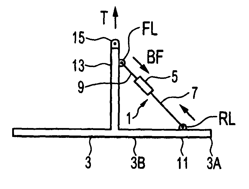
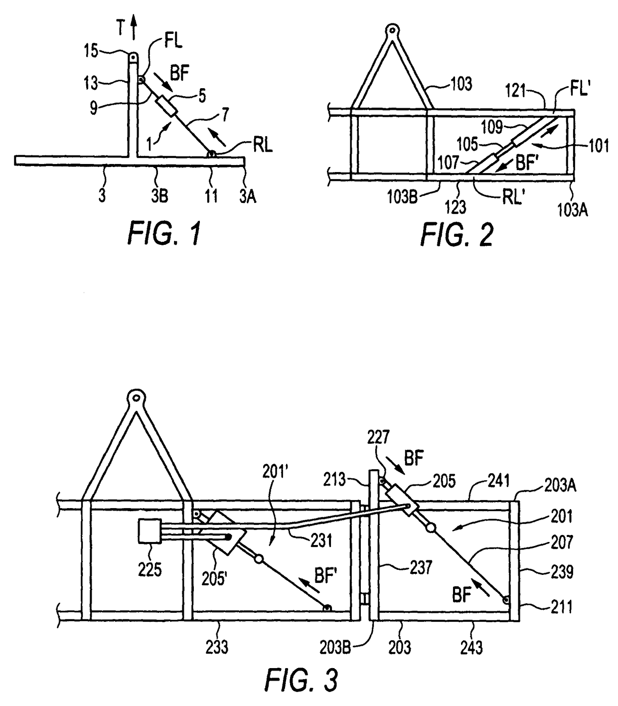
[0027]FIGS. 1 and 2 schematically illustrate diagonal brace apparatuses 1, 101 for an implement frame comprising a bias element connectable to front and rear locations on the implement frame and operative to exert a bias force resisting rearward movement of an outer end of the implement frame with respect to an inner end of the implement frame when connected to the implement frame.

[0028]In the diagonal brace apparatus 1 of FIG. 1 the bias element 5 is adapted at a first end thereof for connection to a front location FL on a front portion of the implement frame 3 and adapted at a second end thereof for connection to a rear location RL on a rear portion of the implement frame 3 that is laterally offset from the front location FL toward an outer end 3A of the implement frame relative to the front location FL. The illustrated bias element 5 is attached at one end thereof to an inside end of a first brace member 7 and at an opposite end thereof to an inner end of a second brace member 9,...


PUM


Abstract

A diagonal brace apparatus for an implement frame includes a bias element connected to a front location on a front portion of the implement frame and connected to a rear location on a rear portion of the implement frame laterally offset from the front location. The bias element is operative to exert a bias force resisting rearward movement of an outer end of the implement frame with respect to an inner end of the implement frame. Conveniently the bias element is provided by a hydraulic cylinder which exerts a bias force and can extend to allow the frame to flex to reduce shock loading on the implement when excessive forces are exerted on the frame.

Description

[0001]This application is the U.S. national phase of International Application No. PCT / CA2007 / 000169, filed 6 Feb. 2007, which designated the U.S. and claims priority to Canada Application No. 2,536,551, filed 15 Feb. 2006, the entire contents of each of which are hereby incorporated by reference.[0002]This invention is in the field of implements such as are used in agriculture where the implement extends laterally from a towing vehicle, and in particular the frames of such implements.BACKGROUND[0003]Agricultural implements such as cultivators, seeders, and the like commonly comprise a frame configured to extend laterally from a central hitch where a tractor is connected for towing the implement. The frame typically comprises a lateral beam extending generally perpendicular to the path of the implement, and a fore and aft beam extending generally in alignment with the implement path, as for example in the implement generally illustrated in U.S. Pat. No. 5,113,956 to Friesen et al. I...

Claims


Application Information

Patent Timeline
Patent Type & Authority Patents(United States)
IPC IPC(8): A01B61/00A01B51/04
CPCA01B51/04A01B61/00
Inventor BEAUJOT, NORBERT
Owner SEEDMASTER MFG
Why Eureka
Try Eureka