Projector having a cooling passage that cools the light source and outer case

a cooling passage and projector technology, applied in the field of projectors, can solve the problems of insufficient cooling effect, insufficient cooling of the outer case in the vicinity of the light-source lamp, and heating of the outer case, and achieve the effect of reducing heat loss and reducing cooling

Inactive Publication Date: 2005-12-20
SEIKO EPSON CORP
View PDF14 Cites 44 Cited by
  • Summary
  • Abstract
  • Description
  • Claims
  • Application Information

AI Technical Summary

Benefits of technology

[0030]In such a structure, the cooling air fed from the sirocco fan and the cooling duct is exhausted by the exhaust fan that is arranged perpendicularly to the cooling duct, so that the cooling passage can be more securely formed, whereby the cooling air is promptly exhausted and the outer case is cooled more efficiently.

Problems solved by technology

However, since the cooling air is exhausted via a ballast (lamp-driving circuit), the cooling air is warmed while passing through the ballast, so that a sufficient cooling effect cannot be obtained.
In particular, the cooling air is to cool only the light-source lamp, so that part of the outer case in the vicinity of the light-source lamp is insufficiently cooled.
As a consequence, heat is produced in the vicinity of the light-source lamp, thereby posing a problem that the outer case is heated up.

Method used


Image

  • Projector having a cooling passage that cools the light source and outer case
  • Projector having a cooling passage that cools the light source and outer case
  • Projector having a cooling passage that cools the light source and outer case

Examples


Embodiment Construction

[0043]An embodiment of the present invention will be described below with reference to the drawings.

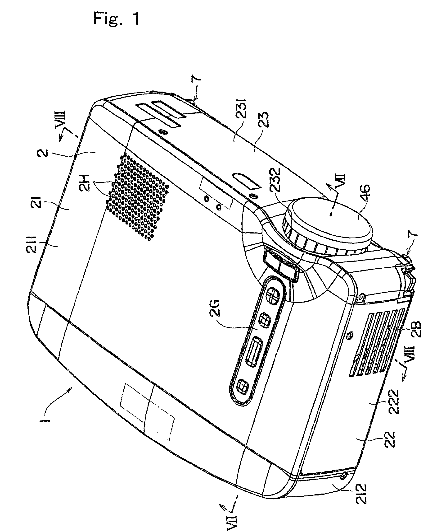
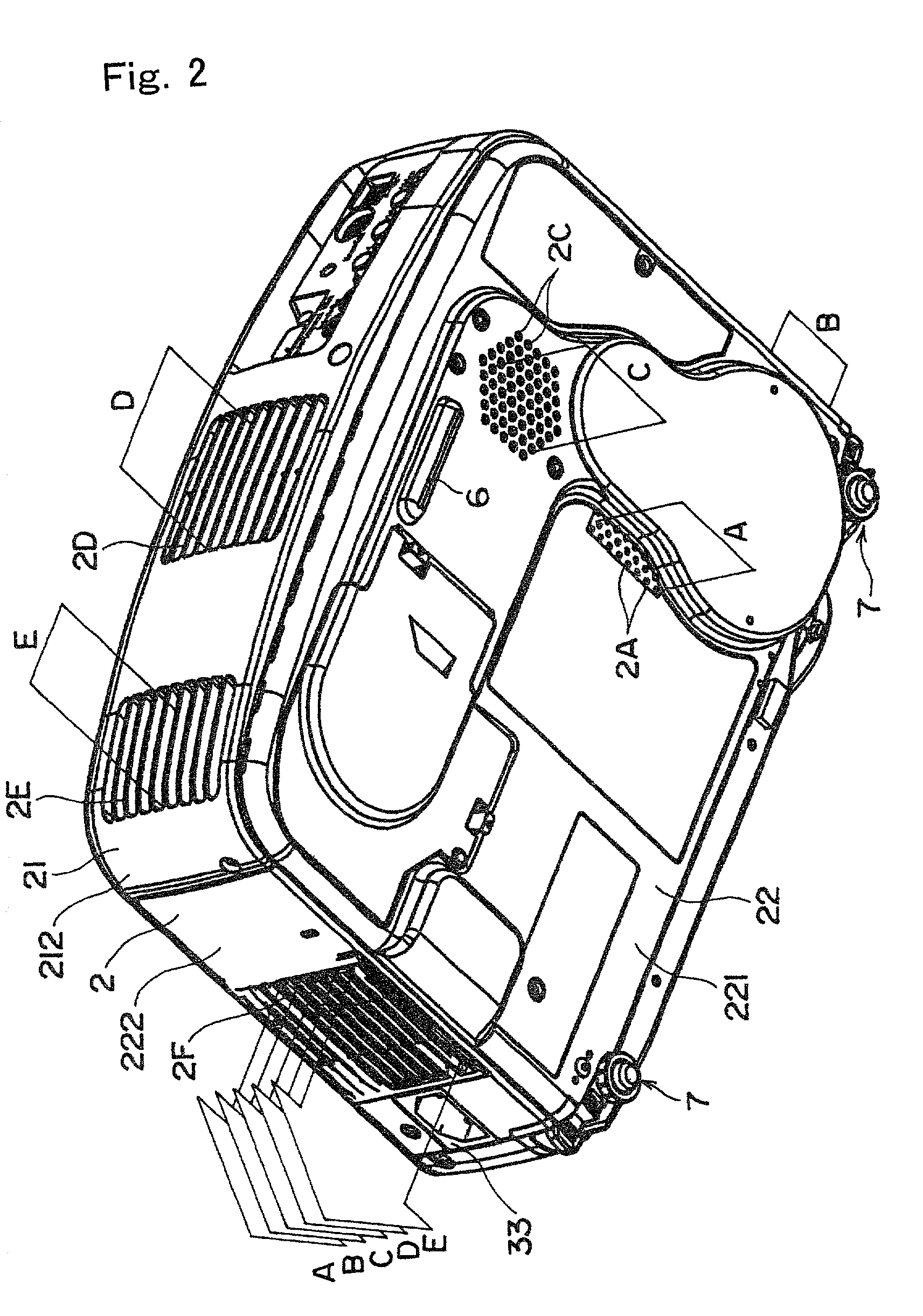
[0044]FIG. 1 is a perspective view of a projector 1 according to the embodiment as viewed from the top of the projector; FIG. 2 is a perspective view of the projector 1 as viewed from the bottom of the projector; and FIG. 3 is a perspective view illustrating the inside of the projector 1.

[0045]Referring now to FIGS. 1 to 3, the projector 1 includes a substantially rectangular box-shaped outer case 2, a power supply unit 3 accommodated inside the outer case 2, and an optical unit 4 also arranged inside the outer case 2 in a planar L-shaped configuration when viewed vertically.

[0046]The outer case 2, as shown in FIG. 4, is formed of an upper case 21 made of a synthetic resin, a lower case 22 made of a metal, such as aluminum, and a front case 23 also made of a metal, such as aluminum, which are fixed to each other with screws.

[0047]The upper case 21 is constructed of a top-face part 211...


PUM


Abstract

The invention provides a projector that is capable of efficiently cooling an outer case along with a light source device. The projector includes an outer case that accommodates a light source device and a cooling passage that is formed in the vicinity of the light source device to cool the outer case. Therefore, the inside of the outer case and the vicinity of the light source device are cooled by the cooling passage so as to cool the outer case efficiently. Also, since the cooling passage is arranged in the vicinity of the light source device, the light source device can also efficiently be cooled. As a result, a temperature rise in the light source device can be restrained so as to cool the outer case more efficiently.

Description

BACKGROUND OF THE INVENTION[0001]1. Field of Invention[0002]The present invention relates to a projector for forming a projected image by magnifying and projecting luminous flux emitted from a light source device after the luminous flux is modulated.[0003]2. Description of Related Art[0004]Recently, projectors have been used in a greater variety of environments. In addition to using projectors for presentations in office meetings or meetings on business trips, projectors are also used at technical meetings in research and development divisions for capturing CAD / CAM / CAE data therein in order to magnify and project the data, for example. Projectors are also used at various seminars and learning courses, as well as in school classes where audiovisual education is performed. Projectors are also used for studying therapeutic methods and for performing medical guidance by projecting medical images and data, such as CT scans and MRI. Projectors are also used for efficiently addressing exhi...

Claims


Application Information

Patent Timeline
Patent Type & Authority Patents(United States)
IPC IPC(8): H04N5/74G03B21/16
CPCH04N9/3141H04N5/7441
Inventor ITO, SHINSUKETAKIZAWA, TAKESHI
Owner SEIKO EPSON CORP
Why Eureka
Try Eureka