
Manufacturing method and injection molding system for multi-color molded article

a manufacturing method and injection molding technology, applied in the field of manufacturing methods and injection molding systems for multi-color molded articles, can solve the problems undesired products, and particularly acute problems, and achieve the effect of avoiding the problem of high cost and lack of versatility, and preventing the production of undesired molded articles

Active Publication Date: 2017-05-23
FANUC LTD
View PDF27 Cites 4 Cited by
  • Summary
  • Abstract
  • Description
  • Claims
  • Application Information

AI Technical Summary

Benefits of technology

[0016]Accordingly, the object of the present invention is to provide a manufacturing method for a multi-color molded article and an injection molding system, capable of avoiding the problem of high cost and lack of versatility due to the use of custom-made injection molding machines and molds and of preventing production of undesired molded articles due to penetration of resins of second and subsequent colors between molded articles and insert molds, which may be caused unless the molded articles and insert molds are in close contact with one another.
[0028]According to the present invention, there may be provided a manufacturing method for a multi-color molded article and an injection molding system, capable of avoiding the problem of high cost and lack of versatility due to the use of custom-made injection molding machines and molds and of preventing production of undesired molded articles due to penetration of resins of second and subsequent colors between molded articles and insert molds, which may be caused unless the molded articles and insert molds are in close contact with one another.

Problems solved by technology

The method (1) has a problem that the injection molding machine and mold are usually custom-made, so that they are costly and not versatile.
Since the transferred molded article is not in close contact with the destination mold surface, however, resins of second and subsequent colors may penetrate between the molded article and the mold surface, possibly resulting in an undesired product.
This problem is particularly acute for optical elements, exterior parts, and other products whose surface shapes are critical.

Method used


Image

  • Manufacturing method and injection molding system for multi-color molded article
  • Manufacturing method and injection molding system for multi-color molded article
  • Manufacturing method and injection molding system for multi-color molded article

Examples


embodiment 1

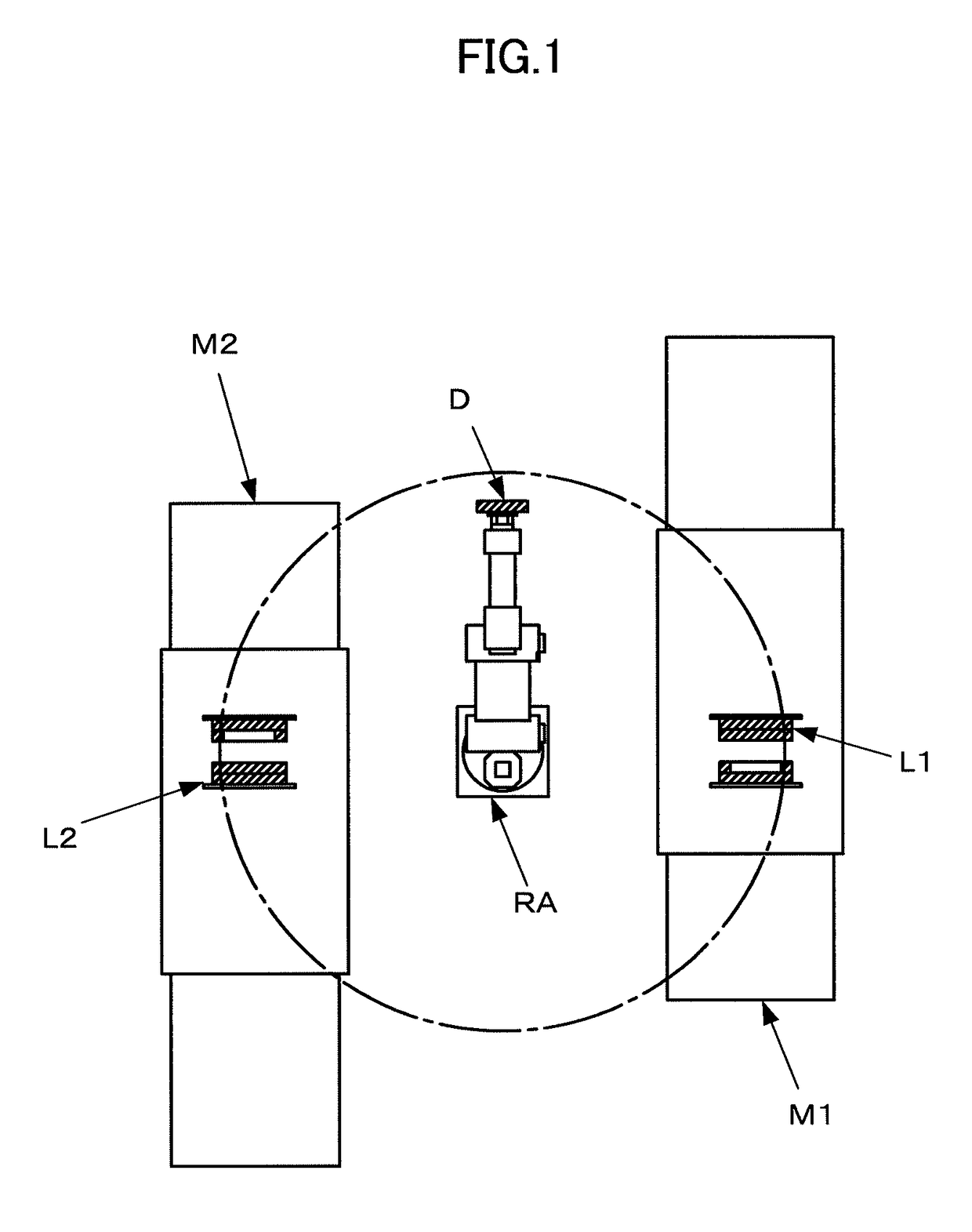
[0036]An example of an injection molding system configured to perform two-color molding with a single insert mold D alternately exchanged between two injection molding machines M1 and M2 will be described with reference to FIG. 1.

[0037]This injection molding system comprises the first and second injection molding machines M1 and M2, a robot, and a controller (not shown). The robot serves to attach and detach an insert mold D to and from molds L1 and L2 of the injection molding machines M1 and M2. The controller controls the first and second injection molding machines M1 and M2 and the robot. The controller controls an insert mold attaching / detaching mechanism and an insert mold conveying mechanism, as well as the injection molding machines M1 and M2 and the robot.

[0038]The insert mold attaching / detaching mechanism comprises, for example, guide pins, ball screws, etc., attached to the molds L1 and L2. The insert mold D can be attached to, or detached from, the molds L1 and L2 by driv...

embodiment 2

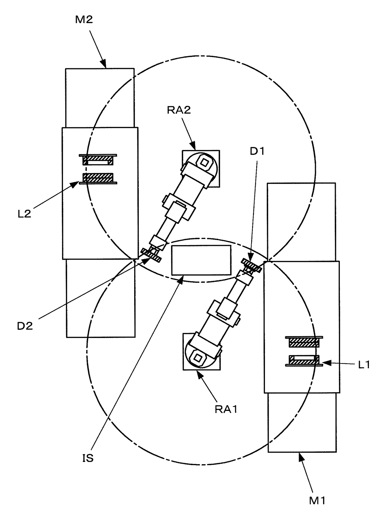
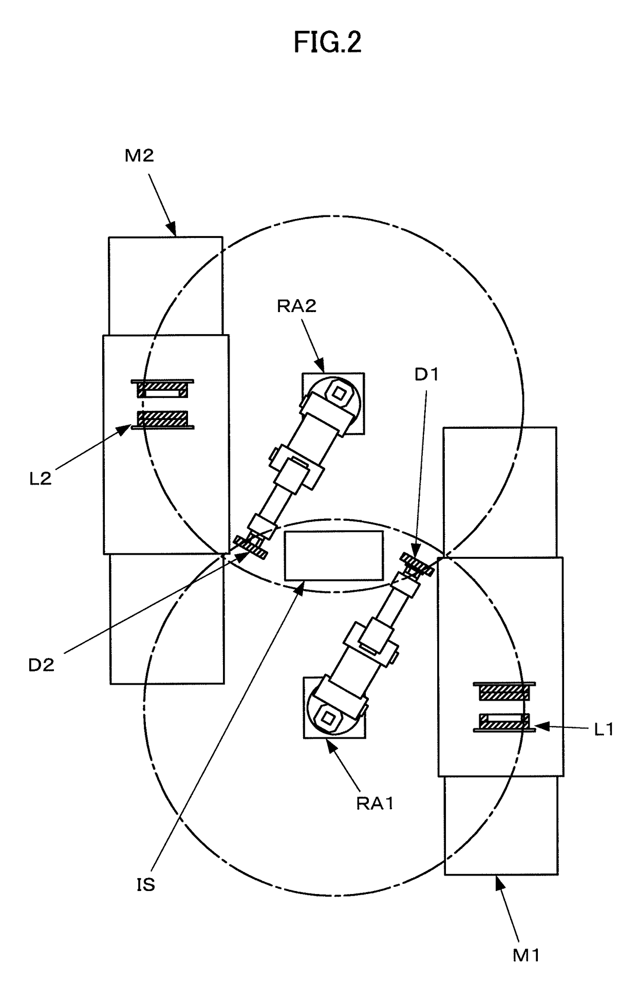
[0042]An example of an injection molding system configured to perform two-color molding with two insert molds D1 and D2 alternately exchanged between two injection molding machines M1 and M2 will be described with reference to FIG. 2.

[0043]While the single robot (robot arm) is used in the example shown in FIG. 1, two robots are used in the example shown in FIG. 2.

[0044]First, a first insert mold D1 is mounted in a mold L1 of the first injection molding machine M1, and a second insert mold D2 with a primary molded article is mounted in a mold L2 of the second injection molding machine M2. The first and second injection molding machines M1 and M2 individually perform injection molding. Thereafter, an arm RA1 of a first robot takes out the first insert mold D1 with the primary molded article from the mold L1 of the first injection molding machine M1 and transports it to an intermediate station IS. At the same time, an arm RA2 of a second robot disengages the second insert mold D2, from...

embodiment 3

[0048]An example of an injection molding system configured to perform three-color molding with two insert molds D1 and D2 alternately exchanged between three injection molding machines M1, M2 and M3 will be described with reference to FIG. 3.

[0049]As in Embodiment 1 (FIG. 1), a single robot (robot arm) is used in this injection molding system. FIG. 3 shows how an arm RA of the robot is transporting a second insert mold D2, from which a molded article is removed after molding by the third injection molding machine M3, to a mold L1 of the first injection molding machine M1 while the second injection molding machine M2 is performing molding for a second color by means of the first insert mold D1 mounted therein. Thus, the availability of the arm RA of the robot can be enhanced by removing the other insert mold (second insert mold D2 in the state of FIG. 3) from molds L1, L2 and L3 of the injection molding machines, transporting it, and attaching it to the molds L1, L2 and L3 by means o...


PUM

PropertyMeasurementUnit
colorsaaaaaaaaaa
coloraaaaaaaaaa
surface shapesaaaaaaaaaa

Abstract

An injection molding system is configured to produce a multi-color molded article by simultaneously or sequentially injection-molding resins of a plurality of types by means of a plurality of injection molding machines. An insert mold is mounted in a mold of a first injection molding machine and a primary molded article is molded by this injection molding machine. Thereafter, a robot arm takes out the insert mold, along with the primary molded article, from the mold of the injection molding machine and attaches it to a mold of a second injection molding machine. A two-color molded article is injection-molded by the second injection molding machine and removed as a product.

Description

RELATED APPLICATIONS[0001]The present application is based on, and claims priority from, Japanese Application Number 2012-205882, filed, the disclosure of which is hereby incorporated by reference herein in its entirety.BACKGROUND OF THE INVENTION[0002]Field of the Invention[0003]The present invention relates to a manufacturing method and an injection molding system for a multi-color molded article.[0004]Description of the Related Art[0005]In general, multi-color molded articles are assumed to be products that are obtained by simultaneously or sequentially injection-molding resins of a plurality of types or colors. In this specification, however, all those molded articles which are obtained by simultaneously or sequentially injection-molding even resins of the same type or color by means of a plurality of injection units are referred to as multi-color molded articles. Further, the multi-color molding described herein is a method of simultaneously or sequentially injection-molding re...

Claims


Application Information

Patent Timeline
Patent Type & Authority Patents(United States)
IPC IPC(8): B29C45/16
CPCB29C45/162B29C2045/1621
Inventor TAKATSUGI, SATOSHIISHIKURO, TOSHIOMORI, RYOUSUKE
Owner FANUC LTD
Learn More