

POP structures and methods of forming the same
a technology of pop structure and pop structure, applied in the field of integrated circuit applications, can solve the problems of large area, large volume, and difficulty in formation, and achieve the effect of improving the quality of the structure and reducing the difficulty of formation
- Summary
- Abstract
- Description
- Claims
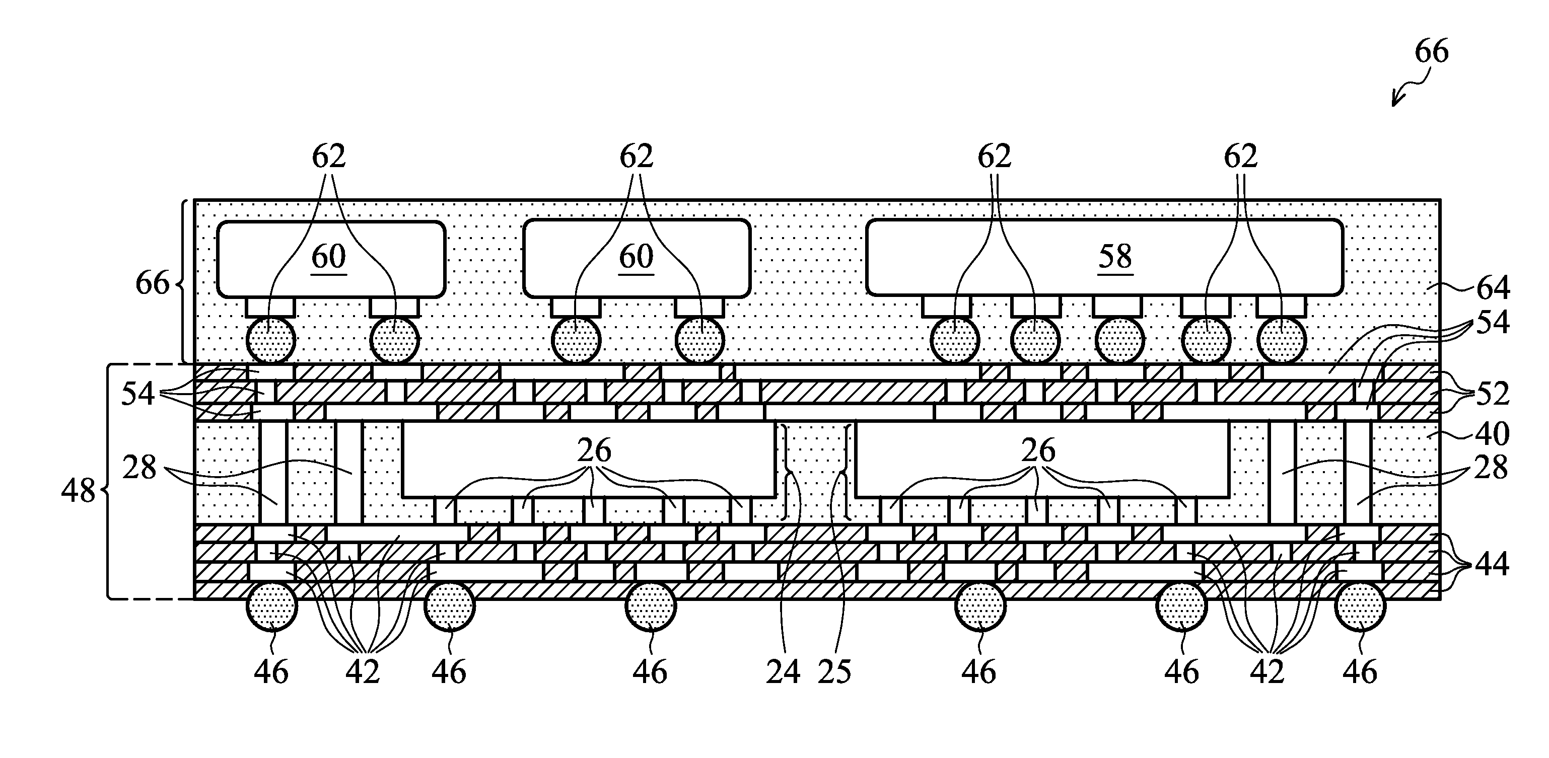
- Application Information
AI Technical Summary
Benefits of technology
Problems solved by technology
Method used
Image

Examples
Embodiment Construction
[0005]The making and using of the embodiments of the disclosure are discussed in detail below. It should be appreciated, however, that the embodiments provide many applicable inventive concepts that can be embodied in a wide variety of specific contexts. The specific embodiments discussed are illustrative, and do not limit the scope of the disclosure.
[0006]A Package-On-Package (POP) structure and the methods of forming the same are provided in accordance with various exemplary embodiments. The intermediate stages of forming the package structure are illustrated. The variations of the embodiments are discussed. Throughout the various views and illustrative embodiments, like reference numbers are used to designate like elements.
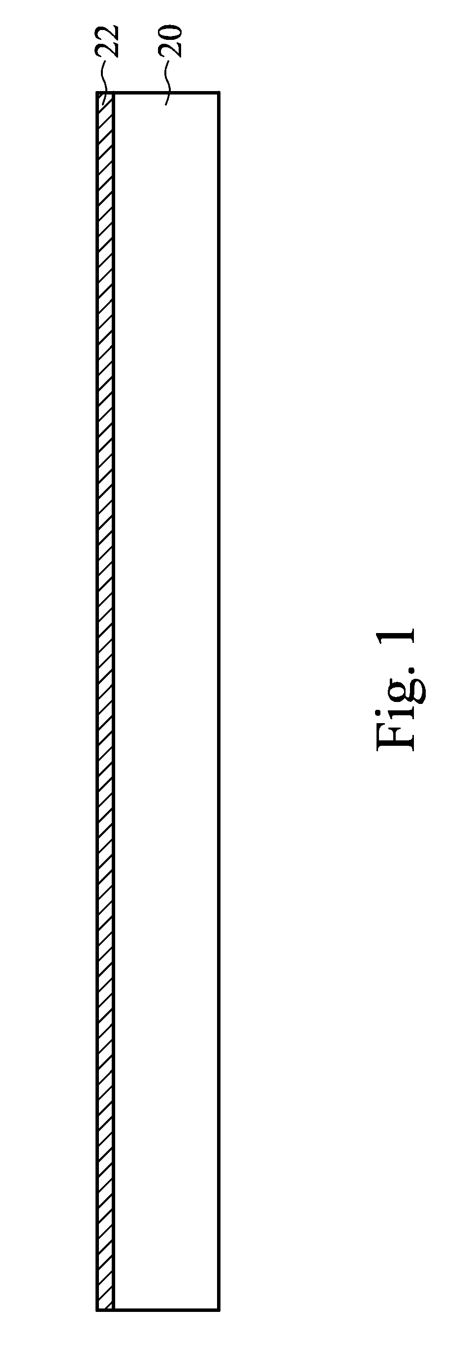
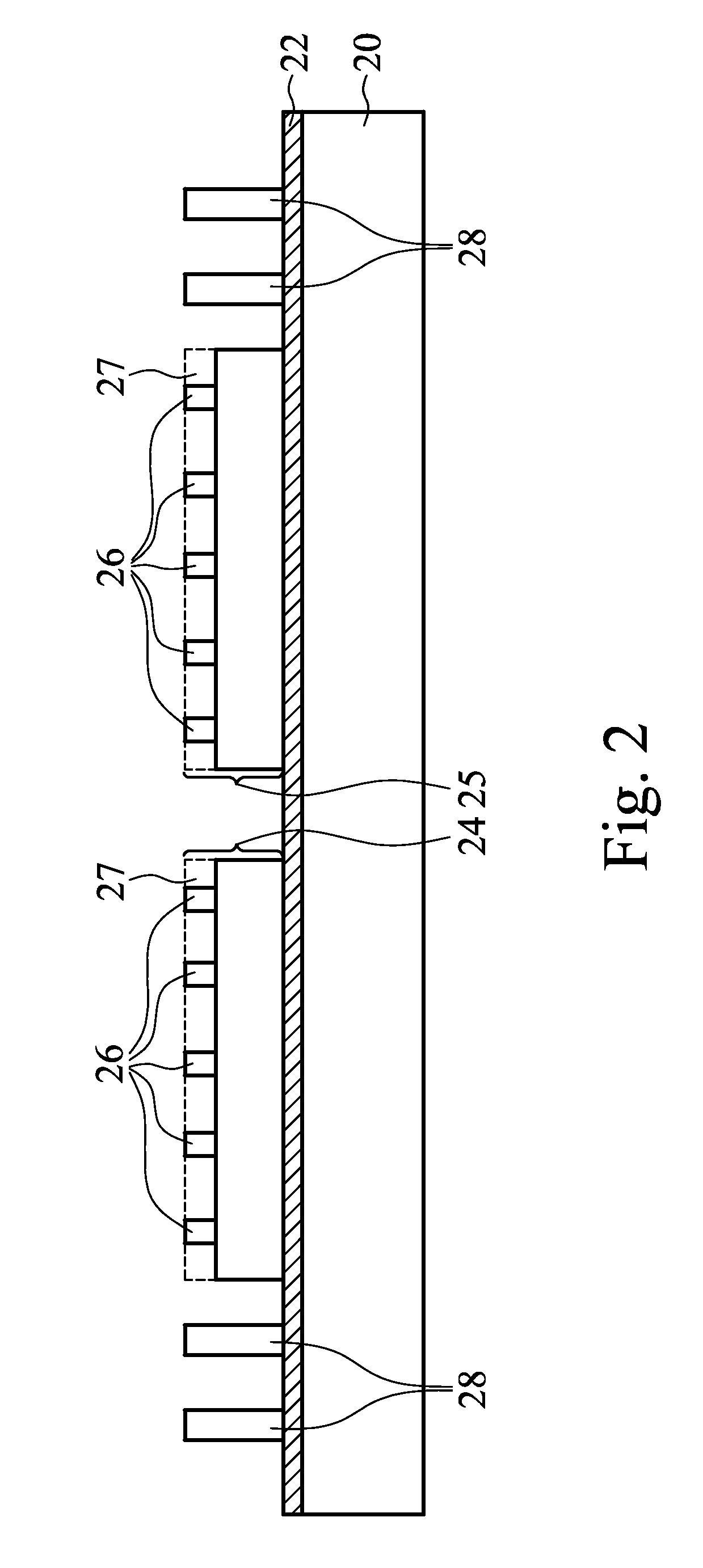
[0007]FIGS. 1 through 10 are cross-sectional views of intermediate stages in the manufacturing of a POP structure in accordance with some exemplary embodiments. FIG. 1 illustrates carrier 20, and adhesive layer 22 on carrier 20. Carrier 20 may be a glass carrie...
PUM
 Abstract
Description
Claims
Application Information