Resin molding, surface mounted light emitting apparatus and methods for manufacturing the same

a technology of surface mounted light emitting apparatus and manufacturing method, which is applied in the direction of insulated conductors, cables, conductors, etc., can solve the problems of inability to reduce the resistance to heat transfer, the light degradation of molding 240/b> is becoming more conspicuous, and the life of the drastically short light emitting device is becoming more and more short, etc., to achieve easy heating and cure, the effect of high fluidity

Active Publication Date: 2009-02-26
NICHIA CORP
View PDF35 Cites 102 Cited by
  • Summary
  • Abstract
  • Description
  • Claims
  • Application Information

AI Technical Summary

Benefits of technology

[0008]With the background described above, an object of the present invention is to provide a surface mounted light emitting apparatus which has long service life and is suitable for mass production, and a molding used to make the surface mounted light emitting apparatus. Another object is to provide a method for easily manufacturing the surface mounted light emitting apparatus and the molding.

Problems solved by technology

Moreover, as the light emitting devices are produced with rapidly increasing output power in recent years, the problem of light degradation of the molding 240 is becoming more conspicuous.
Bonding between the translucent encapsulant resin 250 and the thermoplastic engineering polymer 240, in particular, can be easily destroyed due in part to the weak bonding strength, thus resulting in delamination.
Even when the delamination does not result, discoloration caused by light degradation proceeds and results in drastically short life of the light emitting device.
However, the molding formed from ceramics makes it difficult to insert the lead frame which has high thermal conductivity, and therefore resistance to heat transfer cannot be decreased.
Also because the thermal expansion coefficient is different from that of the translucent encapsulant resin by a factor of 10 or more, sufficient level of reliability has not been achieved.

Method used


Image

  • Resin molding, surface mounted light emitting apparatus and methods for manufacturing the same
  • Resin molding, surface mounted light emitting apparatus and methods for manufacturing the same
  • Resin molding, surface mounted light emitting apparatus and methods for manufacturing the same

Examples


first embodiment

Surface Mounted Light Emitting Apparatus

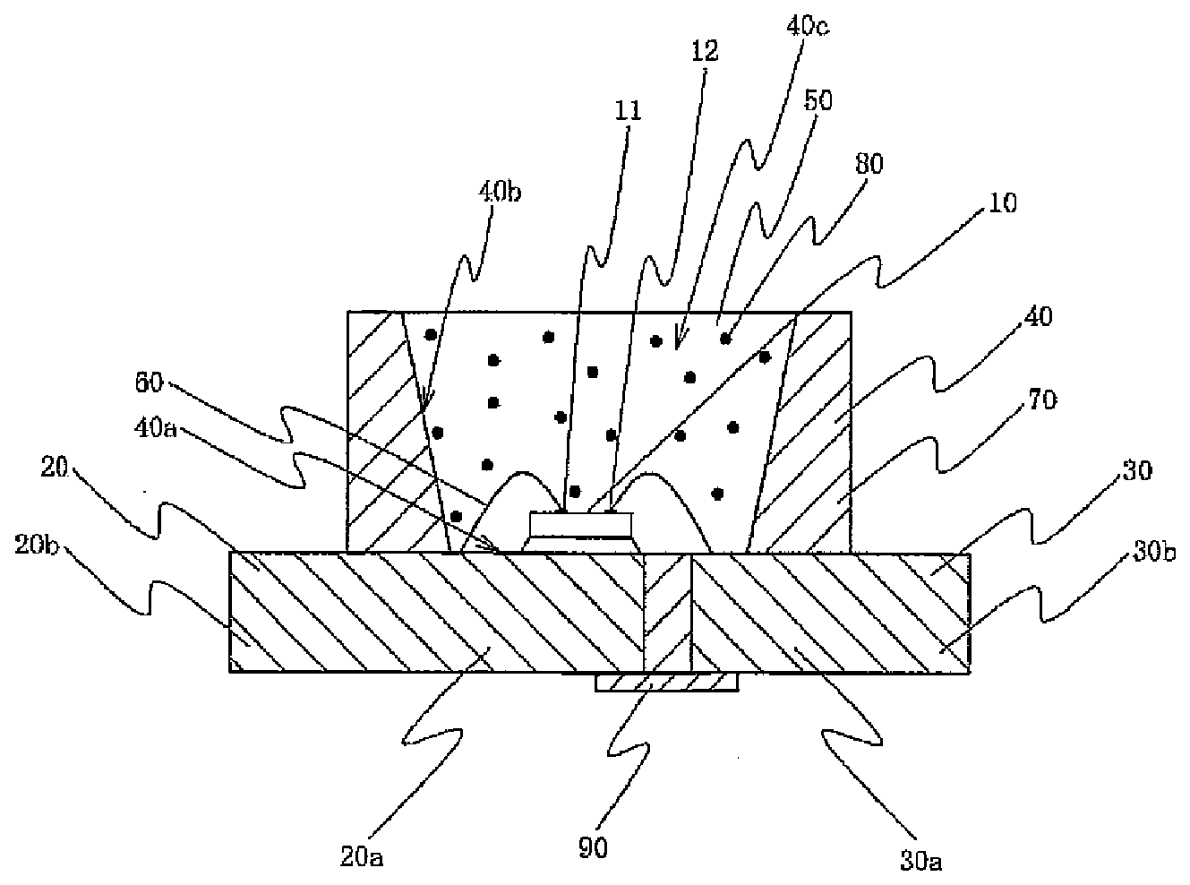
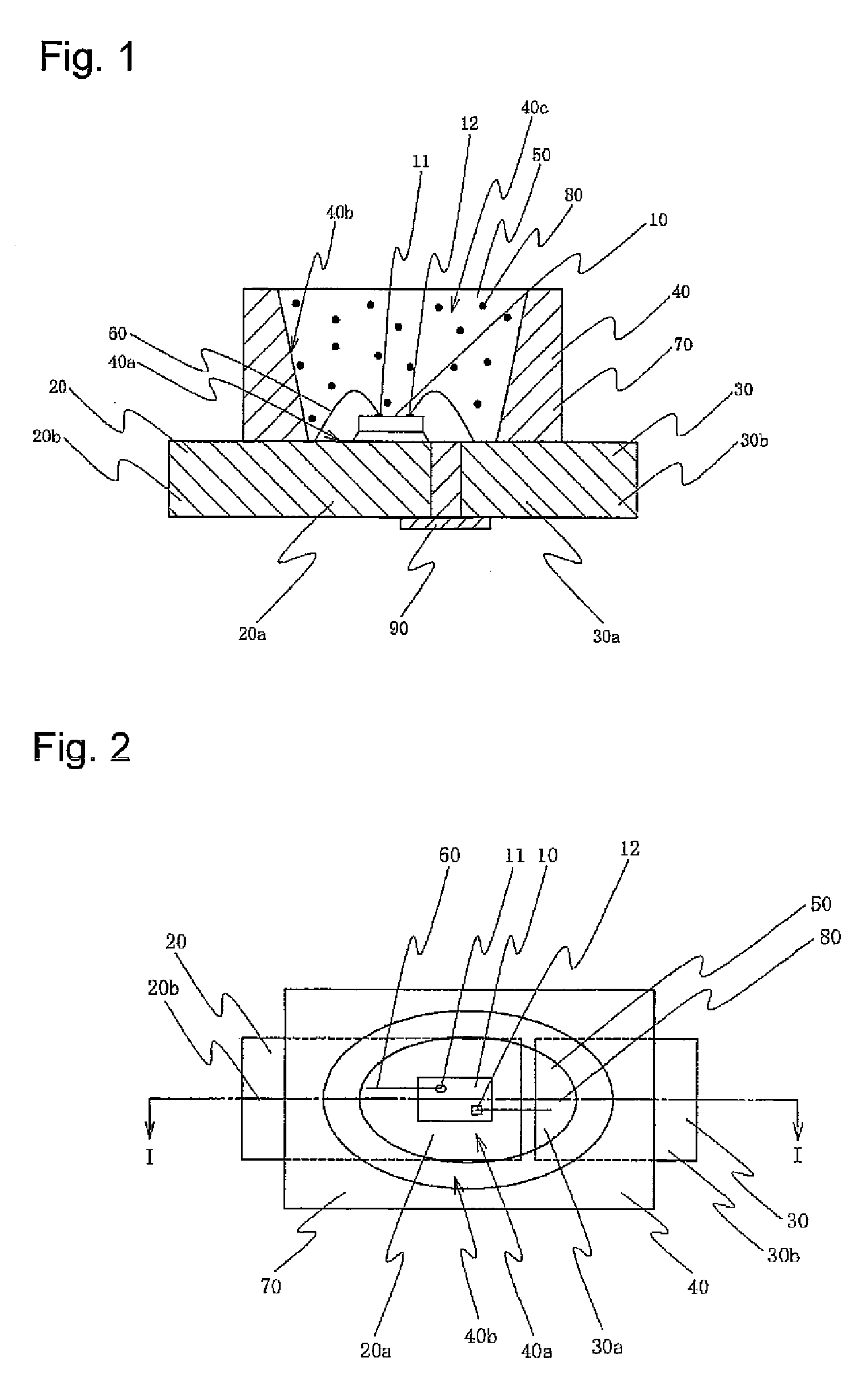
[0094]The surface mounted light emitting apparatus according to the first embodiment will be described with reference to the accompanying drawings. FIG. 1 is a schematic sectional view showing the surface mounted light emitting apparatus according to the first embodiment. FIG. 2 is a schematic plan view showing the surface mounted light emitting apparatus according to the first embodiment. FIG. 1 is a schematic sectional view along line I-I of FIG. 2.

[0095]The surface mounted light emitting apparatus according to the first embodiment comprises a light emitting device 10, a first resin molding 40 whereon the light emitting device 10 is mounted and the second resin molding 50 which covers the light emitting device 10. The first resin molding 40 integrally molds the first lead 20 whereon the light emitting device 10 is mounted and the second lead 30 which is electrically connected to the light emitting device 10.

[0096]The light emitting device 10...

second embodiment

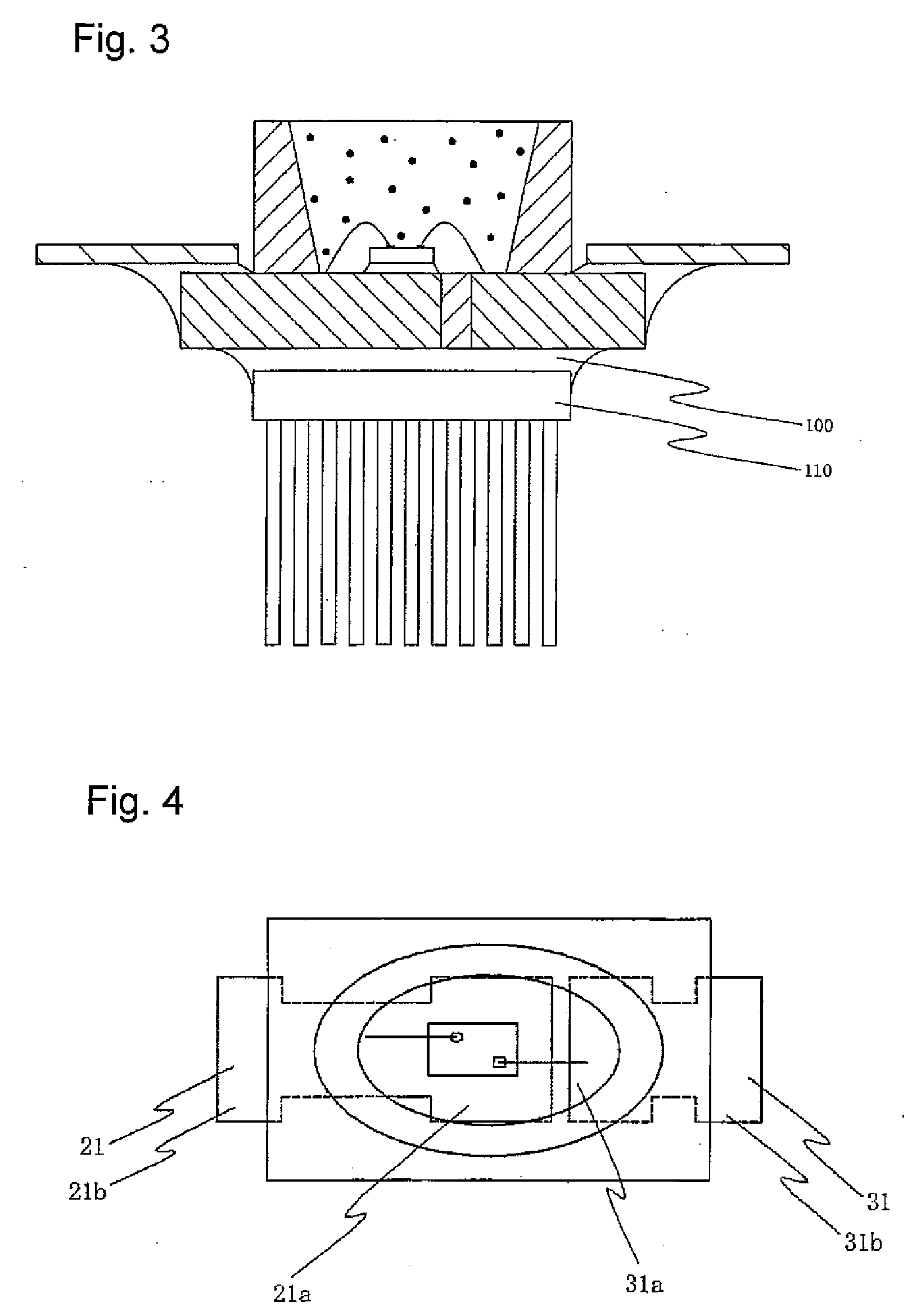
[0143]The surface mounted light emitting apparatus according to the second embodiment will now be described. Aspects of the constitution similar to those of the surface mounted light emitting apparatus according to the first embodiment will be omitted. FIG. 4 is a schematic plan view showing the surface mounted light emitting apparatus according to the second embodiment.

[0144]In the surface mounted light emitting apparatus, surfaces of the first lead 21 and the second lead 31 are roughened so as to increase the contact area with the first resin molding 40. This makes it possible to prevent the first lead 21 and the second lead 31 from coming off the first resin molding 40.

third embodiment

[0145]The surface mounted light emitting apparatus according to the third embodiment will now be described. Aspects of the constitution similar to those of the surface mounted light emitting apparatus of the first embodiment will be omitted. FIG. 5 is a schematic sectional view showing the surface mounted light emitting apparatus according to the third embodiment.

[0146]The surface mounted light emitting apparatus employs the first lead 22 and the second lead 32 which are formed in thin flat plates. This constitution makes it possible to provide the surface mounted light emitting apparatus of more compact and thin construction. The thin flat plate may be formed in rectangular shape as in the first embodiment, or may be roughened as in the second embodiment.


PUM

PropertyMeasurementUnit
wavelengthsaaaaaaaaaa

Abstract

The present invention provides a surface mounted light emitting apparatus which has long service life and favorable property for mass production, and a molding used in the surface mounted light emitting apparatus.The surface mounted light emitting apparatus comprises the light emitting device 10 based on GaN which emits blue light, the first resin molding 40 which integrally molds the first lead 20 whereon the light emitting device 10 is mounted and the second lead 30 which is electrically connected to the light emitting device 10, and the second resin molding 50 which contains YAG fluorescent material and covers the light emitting device 10. The first resin molding 40 has the recess 40c comprising the bottom surface 40a and the side surface 40b formed therein, and the second resin molding 50 is placed in the recess 40c. The first resin molding 40 is formed from a thermosetting resin such as epoxy resin by the transfer molding process, and the second resin molding 50 is formed from a thermosetting resin such as silicone resin.

Description

BACKGROUND OF THE INVENTION[0001]1. Field of the Invention[0002]The present invention relates to a surface mounted light emitting apparatus used in illumination apparatus, display, backlight for mobile phone, auxiliary light source for illumination or other light source for consumer electric apparatus, a resin molding suitable for the surface mounted light emitting apparatus and methods for manufacturing both.[0003]2. Description of the Related Art[0004]A surface mounted light emitting apparatus which employs a light emitting device is compact, has high power efficiency and emits light of clear color. The light emitting device is also free from burnout, because it is a semiconductor device. It also has an excellent initial drive characteristic, and high durability against vibration and repetitive cycles of turning on and off. Because of such excellent characteristics, light emitting apparatuses which use light emitting devices such as light emitting diode (LED) or laser diode (LD) a...

Claims


Application Information

Patent Timeline
Patent Type & Authority Applications(United States)
IPC IPC(8): H01L21/56H01L33/00H01B7/00H01L33/48H01L33/62H01L33/64
CPCH01L33/486H01L33/56H01L33/64H01L33/647H01L2224/32245H01L2224/48091H01L2224/48247H01L2224/73265H01L2924/01004H01L2924/01012H01L2924/0102H01L2924/01025H01L2924/01057H01L2924/01063H01L2924/01078H01L2924/01079H01L2924/3025H01L24/48H01L24/45H01L2924/01066H01L2924/01067H01L2924/01322H01L2224/45144H01L33/26H01L33/32H01L33/34H01L33/44H01L33/62H01L2924/00014H01L2924/00012H01L2924/12035H01L2924/12042H01L2924/12036H01L2924/12041H01L24/73H01L2924/181H01L2924/00H01L2933/0033H01L2933/005H01L2933/0066
Inventor KURAMOTO, MASAFUMIKISHIMOTO, TOMOHISA
Owner NICHIA CORP
Why Eureka
Try Eureka