
System and method for mandrel-less electrospinning

a technology of mandrels and electrospinning, applied in the field of systems and methods for mandrel-less electrospinning, can solve the problems of limited long-term outcome of these procedures, myocardial infarction and ischemia, morbidity and mortality worldwide, etc., and achieve the effect of preventing kinking or distortion of geometry and/or shap

Active Publication Date: 2017-05-23
UNIVERSITY OF PITTSBURGH
View PDF49 Cites 4 Cited by
  • Summary
  • Abstract
  • Description
  • Claims
  • Application Information

AI Technical Summary

Benefits of technology

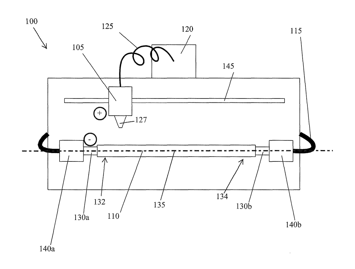
[0006]For the above and other reasons, a need has been identified for devices and methods that can provide enhanced AVGs and other graft devices for mammalian patients. Desirably, the devices will improve long term patency and minimize surgical and device complications. Developing a reliable means to prevent the early events of the IH process and other luminal narrowing responses can contribute to improvements in the outcome of arterial bypass and other graft procedures. Therefore, systems and methods are provided for electrospinning a fiber matrix on a tubular member. For example, a tubular member can be wrapped with the fiber matrix. The tubular member can be, for example, harvested from a human being or animal, such as, a vein, artery, urethra, intestine, esophagus, trachea, bronchi, ureter, duct, or fallopian tube. The tubular member can be, for example, an artificial graft, compatible for use within the body of a patient. The tubular member is wrapped with a covering such as a fiber matrix, typically with a durable or biodegradable (also referred to as bioerodible or bioresorbable) polymer about a circumference of the tubular member.
[0007]The fiber matrix can be deposited on the tubular member by electrospinning Typically, electrospinning involves insertion of a mandrel into the tubular member to support or hold open the tubular member while also providing a charged surface for creation of an electrical potential. The mandrel may also be used to transmit motion to the tubular member, such as translational or rotational motion. The mandrel usually is a mechanical device and oftentimes it is rigid. For example, the mandrel can be a cylindrical rod. A rod-type mandrel can be difficult to insert and / or remove and can damage the tubular member, such as a vein, directly. In addition, prior types of mandrels do not provide for any type of pressure control along the length of the tubular member. Moreover, prior types of mandrels do not easily adapt to different lengths or sizes of tubular members as multiple mandrels are required to accommodate different lengths and sizes of tubular members. Therefore, the system and method for electrospinning a fiber matrix onto a tubular member of the present invention can use a fluid source to provide a fluid mandrel. An advantage of utilizing a fluid mandrel is the provision of a less forceful contact between the tubular member and the mandrel than provided by a mechanical type of mandrel. In addition, a fluid mandrel allows for pressure adjustment across the length of the tubular member allowing for a better match between the mandrel and the tubular member than a mechanical type of mandrel. In addition, a fluid mandrel can allow drugs or other agents to be delivered to and / or embedded in the vein itself, providing a localized agent delivery method.
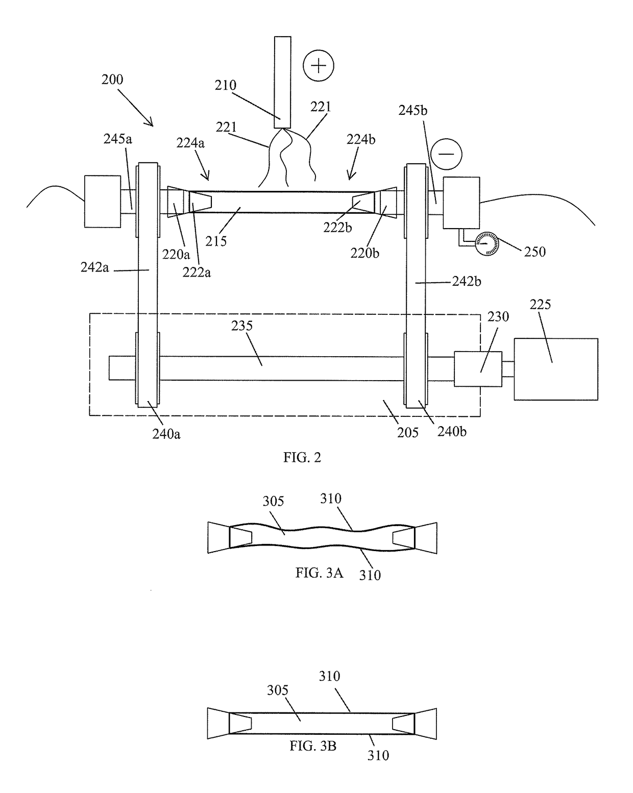
[0026]The system (and / or methods) can also include a synchronous drive system configured to rotate at least one of the first or second plugs. The synchronous drive system can prevent twisting of the tubular member. In some embodiments, the synchronous drive system is a timing belt system.
[0034]In some embodiments, a tensioning force is applied to the tubular member during electrospinning with a fluid mandrel. The tension force can help prevent kinking or distortion of the geometry and / or shape during rotation of the tubular member. In some embodiments, the geometry of the tubular member is controlled by controlling a pressure of the fluid mandrel exerted on an inside surface of the tubular member.

Problems solved by technology

Coronary artery disease, leading to myocardial infarction and ischemia, is a leading cause of morbidity and mortality worldwide.
The long term outcome of these procedures is limited due to occlusion of the graft vessel or anastomotic site as a result of intimal hyperplasia (“IH”), which can occur over a timeframe of months to years.
Development of successful small diameter synthetic or tissue engineered vascular grafts has yet to be accomplished and use of arterial grafts (internal mammary, radial, or gastroepiploic arteries, for example) is limited by the short size, small diameter and availability of these vessels.
Despite their wide use, failure of arterial vein grafts (“AVGs”) remains a major problem: 12% to 27% of AVGs become occluded in the first year with a subsequent annual occlusive rate of 2% to 4%.
Several studies have determined that IH develops, to some extent, in all mature AVGs and this is regarded by many as an unavoidable response of the vein to grafting.
In many cases, this response can lead to stenosis and diminished blood flow through the graft.
A rod-type mandrel can be difficult to insert and / or remove and can damage the tubular member, such as a vein, directly.
In addition, prior types of mandrels do not provide for any type of pressure control along the length of the tubular member.
Moreover, prior types of mandrels do not easily adapt to different lengths or sizes of tubular members as multiple mandrels are required to accommodate different lengths and sizes of tubular members.

Method used


Image

  • System and method for mandrel-less electrospinning
  • System and method for mandrel-less electrospinning
  • System and method for mandrel-less electrospinning

Examples


Embodiment Construction

[0043]In general, electrospinning is a process that uses an electrical charge to draw a fiber, typically from a stream of solution comprised of a polymer dissolved in a solvent, dispensed through a source, for example a nozzle. The fibers that are produced from the electrospinning process are typically on the micro or nano scale. When a voltage is applied to a liquid meniscus facing the outlet of the nozzle and being replenished by an upstream flow, the liquid becomes charged. This charge causes electrostatic repulsion which counteracts the surface tension of the liquid. The liquid stream is attenuated and extruded and at a critical point. The stream dissociates into many other streams and is driven by the same electrostatic repulsion from a source such as a nozzle toward a target, for example, a substrate. Typically, streams dry significantly before the resulting fibers are deposited on a substrate. The electrospinning process can be used to electrospin a fiber matrix onto a tubula...


PUM

PropertyMeasurementUnit
voltageaaaaaaaaaa
voltageaaaaaaaaaa
pressureaaaaaaaaaa

Abstract

A system for electrospinning a fiber matrix on a tubular member includes at least one nozzle, a tubular member in a spaced relationship to the at least one nozzle, and a fluid source for pressurizing a lumen of the tubular member. An electrical potential is applied between the at least one nozzle and either the tubular member or fluid from the fluid source. The electrical potential draws at least one fiber from the at least one nozzle to the tubular member.

Description

CROSS-REFERENCE TO RELATED APPLICATION[0001]This application is a National Phase of International Application No. PCT / US2011 / 66905 filed Dec. 22, 2011, which claims benefit of priority to U.S. Provisional Application No. 61 / 427,993 filed Dec. 29, 2010, the contents of which are hereby incorporated herein by reference in their entirety.FIELD OF THE INVENTION[0002]The invention relates generally to systems and methods for mandrel-less electrospinning, and more particularly, to systems and methods for mandrel-less electrospinning a fiber matrix on a tubular member, such as, for example, a vein or artificial graft.BACKGROUND OF THE INVENTION[0003]Coronary artery disease, leading to myocardial infarction and ischemia, is a leading cause of morbidity and mortality worldwide. Conventional treatment alternatives consist of percutaneous transluminal angioplasty, stenting, and coronary artery bypass grafting (“CABG”). CABG can be carried out using either arterial or venous conduits and is an ...

Claims


Application Information

Patent Timeline
Patent Type & Authority Patents(United States)
IPC IPC(8): B29C47/00A61F2/06A61L27/14A61L27/38A61L27/50D01D5/00D04H1/728
CPCB29C47/0076A61F2/06A61F2/062A61L27/14A61L27/38A61L27/50D01D5/0076D04H1/728A61F2240/001B29C48/142
Inventor MCGRATH, JONSOLETTI, LORENZOEL-KURDI, MOHAMMED S.WAGNER, WILLIAM R.FLAHERTY, J. CHRISTOPHER
Owner UNIVERSITY OF PITTSBURGH
Learn More