Inflatable craft having V-shaped hull and flaps

a technology of inflatable craft and flaps, which is applied in the direction of hulls, vessel salvaging, vessel construction, etc., can solve the problems of craft even having difficulty in getting on the plane, its maximum speed may be severely limited, etc., and achieve the effect of cost-effective both manufactur

Active Publication Date: 2017-05-23
ZODIAC MILPRO INT
View PDF11 Cites 1 Cited by
  • Summary
  • Abstract
  • Description
  • Claims
  • Application Information

AI Technical Summary

Benefits of technology

[0022]Generally, the improved arrangement introduced by the invention in inflatable craft of the type discussed in the introduction is found to be advantageous in respect of ge

Problems solved by technology

However, when a craft of this type is heavily laden, it is found that its maximum speed ma

Method used


Image

  • Inflatable craft having V-shaped hull and flaps
  • Inflatable craft having V-shaped hull and flaps
  • Inflatable craft having V-shaped hull and flaps

Examples


Embodiment Construction

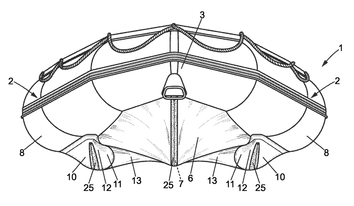
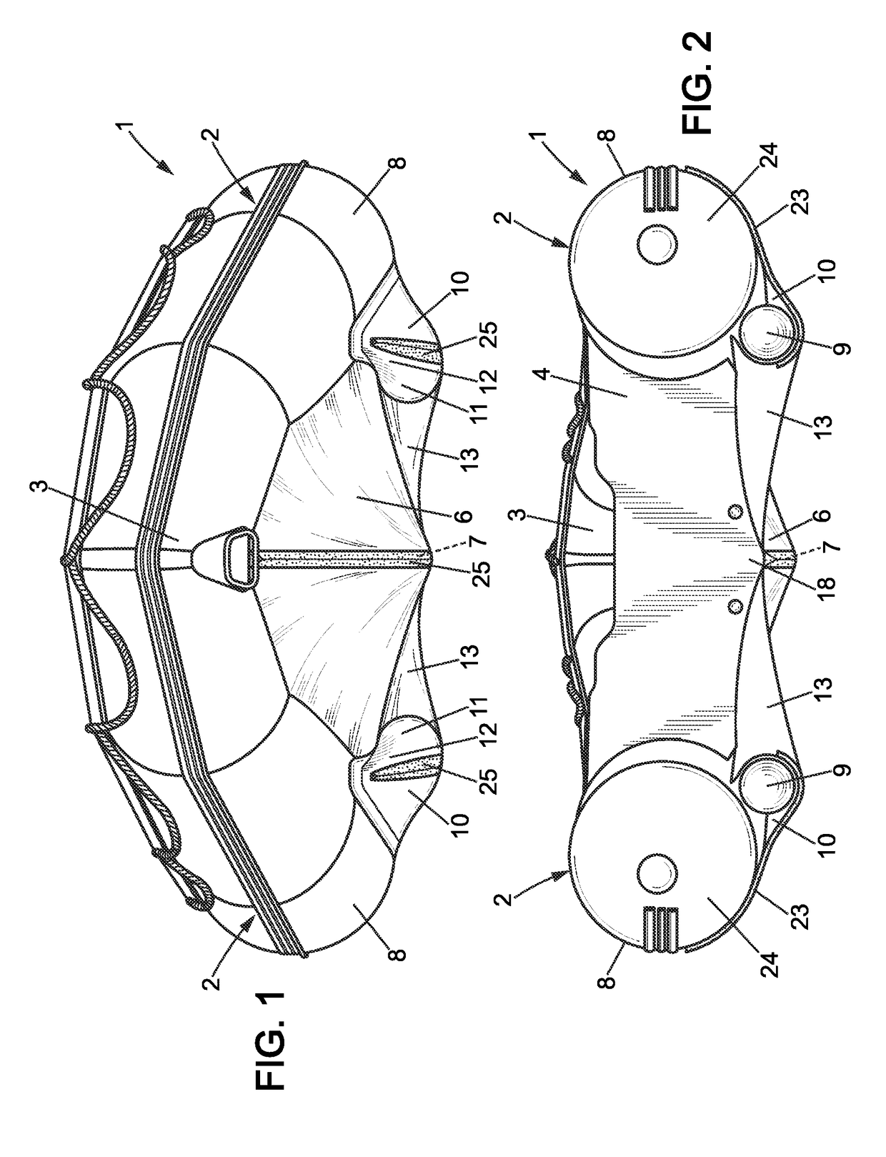
[0031]Referring firstly to FIGS. 1, 2 and 4 to 6, a craft according to the invention comprises an inflatable sponson 1 forming two opposing elongate members, comprised of two substantially parallel rearward portions (two substantially parallel members 2) being substantially parallel to each other and frontward portions that converge and meet towards the front to form a bow 3 (not shown in FIG. 5).

[0032]A transom 4 (shown in FIGS. 2 and 6) links the two members 2 of the sponson 1 close to their rear ends, and is intended to close the rear of the craft in a watertight manner and to support at least one motor or engine, in particular of the outboard type (not shown).

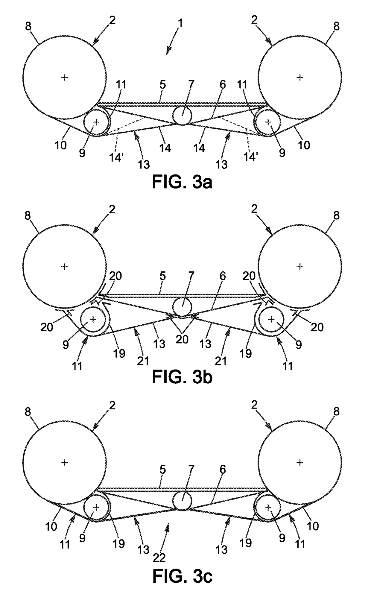
[0033]Along the two members 2 of the sponson 1 of the craft a floor 5 (see FIG. 3a) is held in place, internally and at least transversally, which can be rigid, flexible or foldable, and made in any suitable known manner (slats or panels made of wood or metal or a synthetic material, inflatable bottom, for example).

[0034]A ...


PUM


Abstract

Disclosed is a vessel with two watertight flaps attached in a tensioned state on the two sides of the longitudinal keel, each being under one of the two rear side portions of the V-shaped hull, the outer side edge of each flap being connected under the shell covering the bottom compartment on the same side, and the bottom side edge being connected to the bottom along a line which is angled from the rear to the front and angled toward the lower compartment, with a flap width tapering from the tensioned, free rear edge between the ends at the transom, toward a front portion connected to the bottom and/or to the shell at the connection between the upper and lower compartments, defining, with the latter and the bottom, a channel converging from front to rear and angled toward the rear end of the edge of the V-shaped craft hull.

Description

BACKGROUND OF THE INVENTION[0001]The present invention relates to improvements made to inflatable craft of the type comprising at least one inflatable sponson forming two substantially parallel members meeting towards the front to form a bow, and a transom linking said members and capable of receiving at least one motor or engine, each of said members comprising, at least in the substantially parallel portion thereof, several tubular compartments, each having a substantially circular cross-section, one of which is an upper compartment and one a lower compartment, placed longitudinally next to one another along a lower, circumferential area, facing the other member, of said upper compartment, which has a cross-section greater than that of said lower compartment, held against said upper compartment by a flexible side shell, made from cloth or fabric, which at least partially surrounds it and is firmly fixed to said upper compartment, said flexible shell being secured tangentially to s...

Claims


Application Information

Patent Timeline
IPC IPC(8): B63B1/00B63B7/08B63B1/04B63B41/00
CPCB63B7/082B63B1/042B63B41/00B63B2041/003
Inventor CASSANAS, MARCBOUDEAU, LIONEL
Owner ZODIAC MILPRO INT
Why Eureka
Try Eureka