Driving circuit and driving method

a driving circuit and driving method technology, applied in the direction of electronic switching, pulse technique, power conversion systems, etc., can solve the problems of ringing noise, interference of ringing noise, speeding etc., to speed up the turn-off speed of the switch element and prevent inadvertently turning on the switch element

Active Publication Date: 2017-05-23
ANCORA SEMICON INC
View PDF14 Cites 1 Cited by
  • Summary
  • Abstract
  • Description
  • Claims
  • Application Information

AI Technical Summary

Benefits of technology

[0009]In view of the above, in one embodiment, one of the levels of the driving voltage signal is lower than a zero level. Compared to a traditional method of utilizing a zero-level signal to turn off the switch element, by utilizing a signal whose le

Problems solved by technology

At this time, the driving signal Vg1 changing from a low voltage to a high voltage may generate a ringing noise.
The ringing noise may inte

Method used


Image

  • Driving circuit and driving method
  • Driving circuit and driving method
  • Driving circuit and driving method

Examples


Embodiment Construction

[0024]The present disclosure will now be described more fully hereinafter with reference to the accompanying drawings, in which exemplary embodiments of the disclosure are shown. This disclosure may, however, be embodied in many different forms and should not be construed as limited to the embodiments set forth herein. Rather, these embodiments are provided so that this disclosure will be thorough and complete, and will fully convey the scope of the invention to those skilled in the art. Like reference numerals refer to like elements throughout.

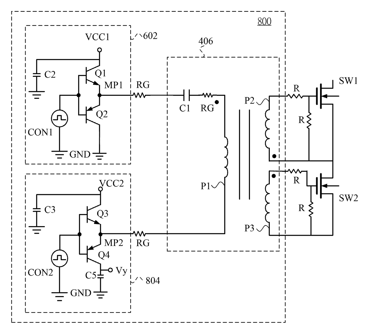
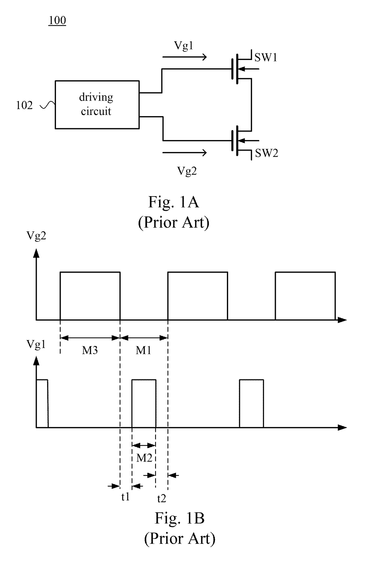
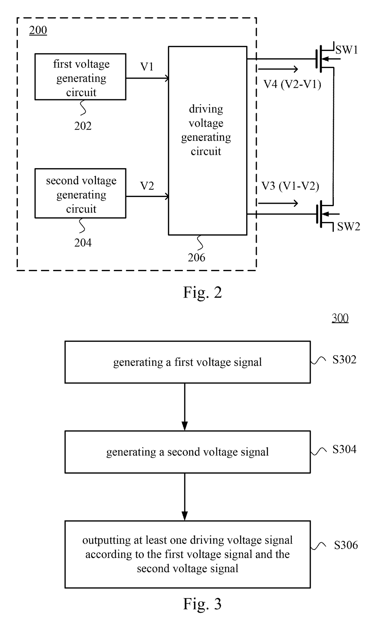
[0025]FIG. 2 is a block diagram illustrating a driving circuit 200 and switch elements SW1 and SW2 according to one embodiment of the present disclosure. The driving circuit 200 is configured to control the switch elements SW1 and SW2. In some embodiments, the switch elements SW1 and SW2 are enhancement GaN (e-GaN) switches, but are not limited thereto.

[0026]As illustrated in FIG. 2, the driving circuit 200 includes a first voltage generating...


PUM


Abstract

A driving circuit configured to control at least one switch element is disclosed in the present disclosure. The driving circuit includes a first voltage generating circuit, a second voltage generating circuit and a driving voltage generating circuit. The first voltage generating circuit is configured to generate a first voltage signal. The second voltage generating circuit is configured to generate a second voltage signal. The driving voltage generating circuit is electrically coupled with the first voltage generating circuit and the second voltage generating circuit. The driving voltage generating circuit outputs at least one driving voltage signal according to the first voltage signal and the second voltage signal. The at least one driving voltage signal comprises three levels. At least one level of the levels is lower than zero level.

Description

BACKGROUND[0001]Technical Field[0002]The present disclosure relates to a driving circuit and a driving method thereof. More particularly, the present disclosure relates to a driving circuit and a driving method, in which the driving circuit and the driving method are configured to generate a driving voltage signal having three levels.[0003]Description of Related Art[0004]FIG. 1A is a block diagram illustrating a conventional converter 100. FIG. 1B is a waveform diagram of driving signals Vg1 and Vg2 of a driving circuit 102 in FIG. 1A. As illustrated in FIG. 1A and FIG. 1B, the driving circuit 102 of the converter 100 is configured to generate the driving signals Vg1 and Vg2, and the driving signals Vg1 and Vg2 are configured to separately control switch elements SW1 and SW2 to be turned on or turned off. In a turn-off duration M1 of the switch element SW2, the driving signal Vg1 provides a high voltage to the switch element SW1 to turn on the switch element SW1. At this time, the d...

Claims


Application Information

Patent Timeline
IPC IPC(8): H03K17/04H01L29/778H03K17/10H03K17/687H01L29/20
CPCH03K17/102H03K17/6871H01L29/2003H01L29/7787H02M1/08H03K17/06H03K2017/066
Inventor CHUANG, PO-CHINHUNG, SHENG-HSI
Owner ANCORA SEMICON INC
Why Eureka
Try Eureka