Recording apparatus and recording method

a recording apparatus and recording method technology, applied in the direction of electrical apparatus, typewriters, printing, etc., can solve the problem that the recording position shift of the recording image in accordance with the setting position shift of the medium cannot be suitably suppressed, and achieve the effect of suppressing the recording position shift of the recording imag

Active Publication Date: 2017-05-30
SEIKO EPSON CORP
View PDF7 Cites 2 Cited by
  • Summary
  • Abstract
  • Description
  • Claims
  • Application Information

AI Technical Summary

Benefits of technology

[0007]An advantage of some aspects of the invention is to suppress recording position shift of a recording image in accordance with setting position shift of a medium.
[0016]According to the aspects of the invention, it is possible to suppress recording position shift of the recording image in accordance with setting position shift of the medium.

Problems solved by technology

However, in the recording apparatus that is disclosed in WO03 / 31190, there are cases in which recording position shift of a recording image in accordance with setting position shift of a medium cannot be suitably suppressed as a result of shift in an attachment position of an imaging unit, blur during image capture or the like.

Method used


Image

  • Recording apparatus and recording method
  • Recording apparatus and recording method
  • Recording apparatus and recording method

Examples


embodiment 1

FIGS. 1 to 8

[0028]Firstly, a recording apparatus according to Embodiment 1 of the invention will be described.

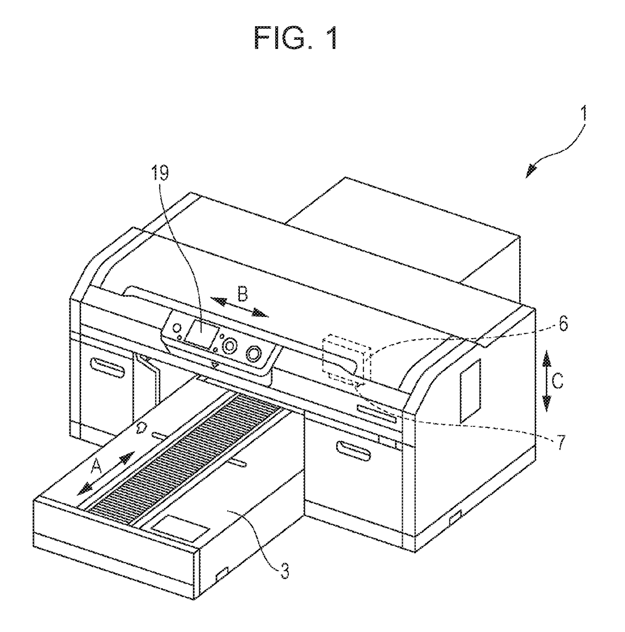
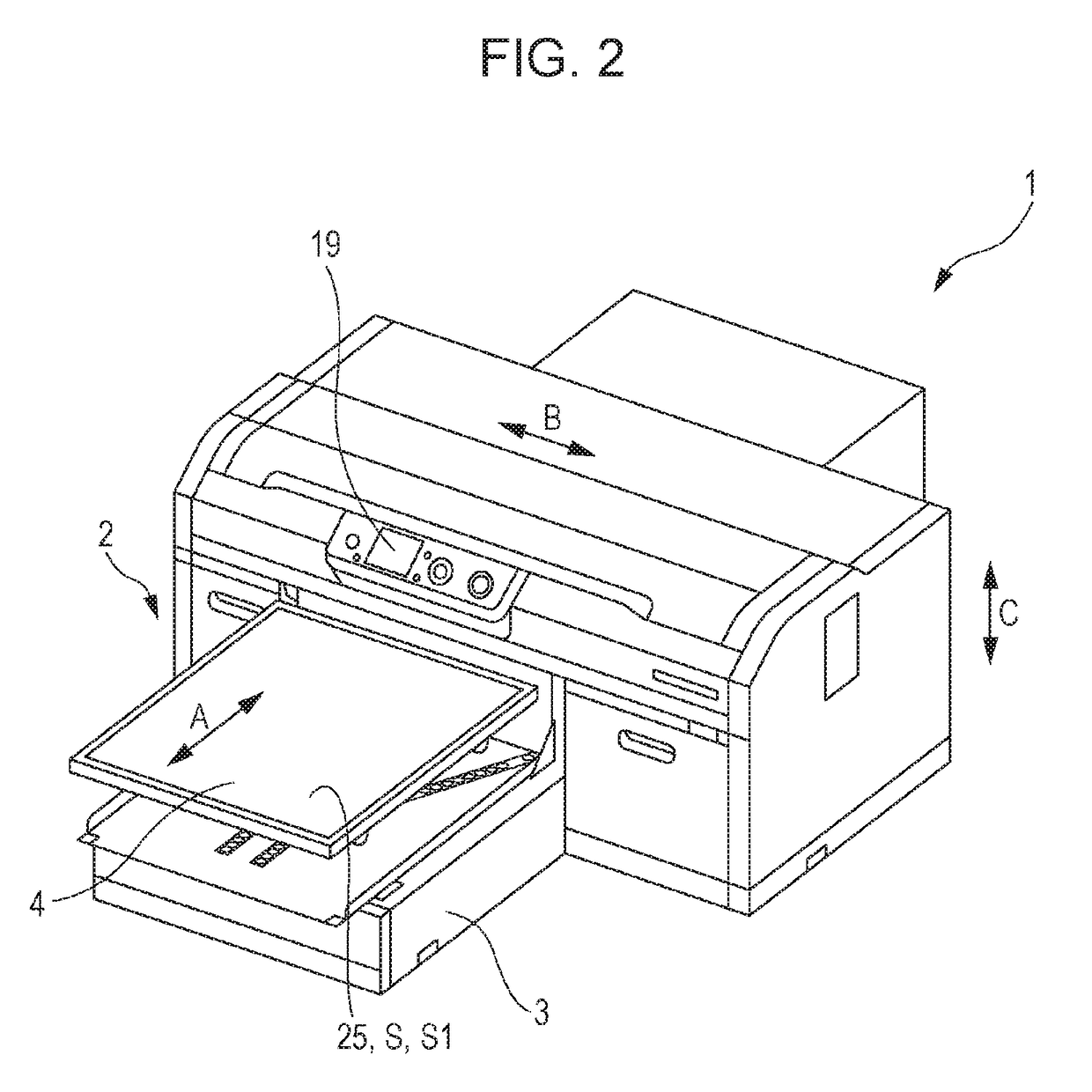
[0029]FIGS. 1 and 2 are schematic perspective views of a recording apparatus 1 of Embodiment 1 of the invention, and of these, FIG. 1 shows a state in which a tray 4, as a setting section of a medium M (refer to FIGS. 5A and 5B) of the recording apparatus 1 of the present embodiment, is in a recording initiation position, and FIG. 2 shows a state in which the tray 4 is in a setting position of the medium M.

[0030]In addition, FIG. 3 is a schematic front view of the recording apparatus 1 of the present embodiment.

[0031]The recording apparatus 1 of the present embodiment is provided with a medium support unit 2, which moves in a movement direction A in a state of supporting the medium M. The medium support unit 2 includes the tray 4, which is a setting section on which it is possible to set the medium M, and is also a support section. The recording apparatus 1 is provided with ...

embodiment 2

FIG. 9

[0077]Next, a recording apparatus according to Embodiment 2 of the invention will be described.

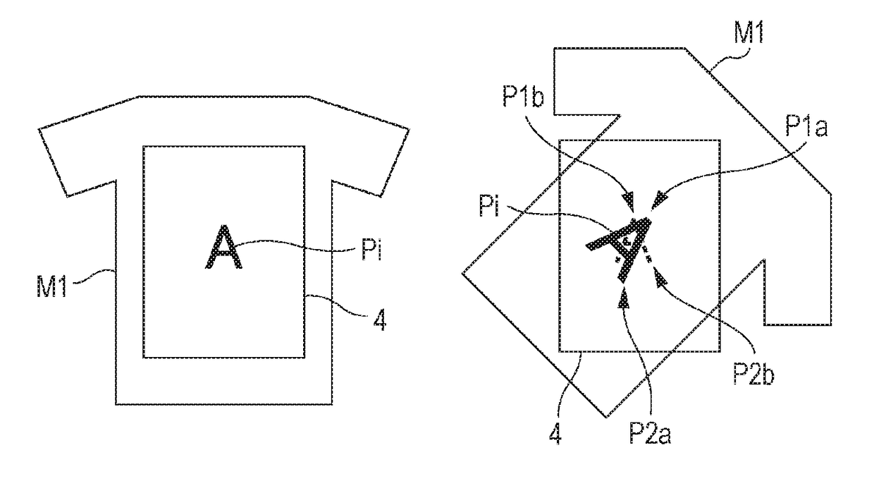
[0078]FIG. 9 is a schematic plan view that shows a state in which the medium M is set in the recording apparatus 1 according to Embodiment 2 of the invention, and is a view that corresponds to FIG. 6 of Embodiment 1. Additionally, the same reference numerals will be given to constituent members that are shared with the abovementioned Embodiment 1, and detailed description thereof will be omitted.

[0079]The recording apparatus 1 of the present embodiment only differs from the recording apparatus 1 of Embodiment 1 in the configuration of the designation section S (S3).

[0080]In the recording apparatus 1 of the present embodiment, the designation section S is configured by the tray 4 and the touch pen 21. To explain in further detail, the touch pen 21 is capable of acquiring positional information (positional information of the tip end section 22 of the touch pen 21 with respect to the tr...


PUM


Abstract

A recording apparatus includes a setting section on which it is possible to set a medium, a recording section that is capable of recording a recording image on a set medium, which is the medium that is set in the setting section on the basis of image data, a designation section that is capable of designating a recording position of the recording image on the set medium, and a control section that causes the recording image to be recorded on the set medium on the basis of the recording position that is designated by the designation section. In a recording apparatus with such a configuration, it is possible to suppress recording position shift of the recording image arises in accordance with setting position shift of a medium.

Description

BACKGROUND[0001]1. Technical Field[0002]The present invention relates to a recording apparatus and a recording method.[0003]2. Related Art[0004]In the related art, a recording apparatus that is capable of recording a recording image on a medium that is set in a setting section, is used. In such a recording apparatus, there are cases in which recording position shift of a recording image arises in accordance with setting position shift of a medium.[0005]In such an instance, for example, International Publication No. WO2003 / 31190 discloses a recording apparatus (an ink jet printing apparatus) that aims to capture an image of a medium (a target printing object) that is set on a bed as a setting section, and suppress recording position shift of a recording image in accordance with setting position shift of a medium on the basis of data that is obtained by capturing an image with an imaging unit.[0006]However, in the recording apparatus that is disclosed in WO03 / 31190, there are cases in...

Claims


Application Information

Patent Timeline
Patent Type & Authority Patents(United States)
IPC IPC(8): H04N1/034H04N1/00
CPCH04N1/034H04N1/00721H04N1/00732B41J3/4078
Inventor KAIEDA, TERUAKI
Owner SEIKO EPSON CORP
Why Eureka
Try Eureka