Molding die and manufacturing method of optical element

a manufacturing method and technology of optical elements, applied in the field of molding dies, can solve the problems of increasing the demand for optical elements made of glass and the demand for performance is becoming more severe, and achieve the effects of suppressing any position shift of the top die, simple configuration, and small eccentricity

Inactive Publication Date: 2010-08-05
KONICA MINOLTA OPTO
View PDF5 Cites 2 Cited by
  • Summary
  • Abstract
  • Description
  • Claims
  • Application Information

AI Technical Summary

Benefits of technology

[0023]According to the present invention, because the glass material is press-molded in the condition in which the top die and the bottom die are pushed and pressed against guiding members due to the thermal expansion of an expansion member, it is possible to effectively suppress any position shift of the top die and the bottom die. As a consequence, it is possible to manufacture optical elements with a simple configuration and with small degrees of eccentricities without having to narrow the selecting options of the materials of the molding dies.

Problems solved by technology

According to the size reduction and increase in accuracy of various types of optical equipments in recent years, the demanded performance of optical elements made of glass is becoming higher, and even the demanded performance is becoming more severe regarding the quantity of shift of the optical axes of two opposing optical surfaces (hereinafter referred to as “degree of eccentricity”).

Method used


Image

  • Molding die and manufacturing method of optical element
  • Molding die and manufacturing method of optical element
  • Molding die and manufacturing method of optical element

Examples


first preferred embodiment

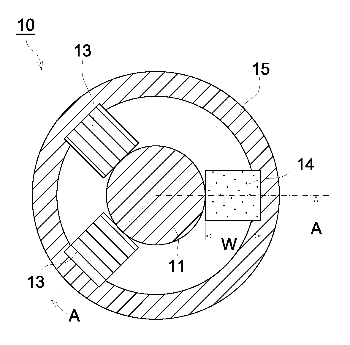
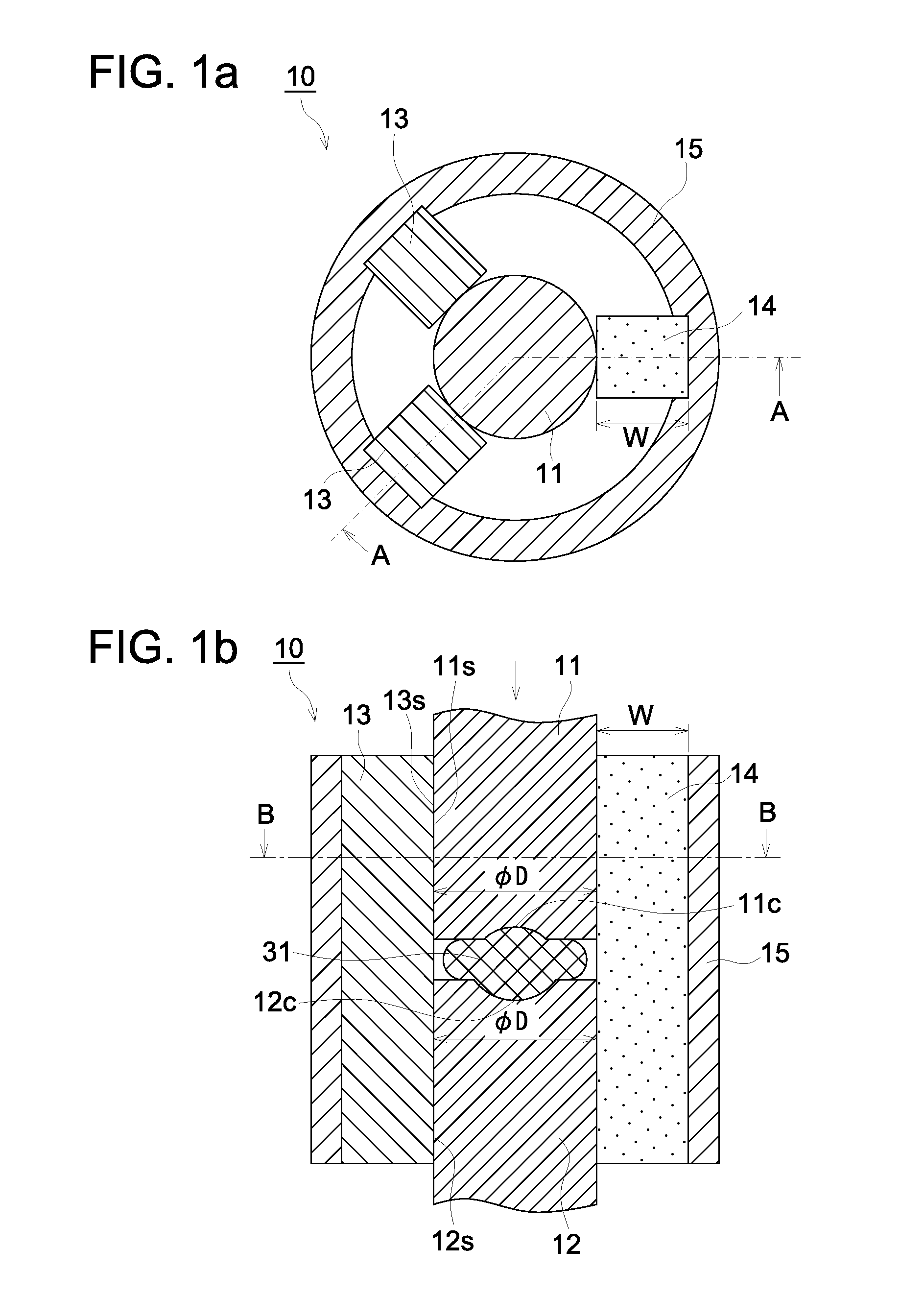
[0056]FIG. 1 is a diagram showing an example of a molding die according to the first preferred embodiment of the present invention, and shows the condition in the process of applying pressure to the glass material. FIG. 1a is a cross-sectional view diagram of a cross-section perpendicular to the direction of pressing (the press axis direction) the glass material and indicates the cross-section at B-B indicated in FIG. 1b. Further, FIG. 1b is a cross-sectional view diagram of a cross-section that is parallel to the press axis direction and indicates the cross-section at A-A indicated in FIG. 1a.

[0057]The molding die 10 shown in FIG. 1 has a top die 11, a bottom die 12, a guiding member 13, an expansion member 14, and a supporting member 15.

[0058]The top die 11 has the first pressure applying surface 11c that has been machined precisely with a shape corresponding to the first optical surface of the optical element and the bottom die 12 has the second pressure applying surface 12c tha...

second preferred embodiment

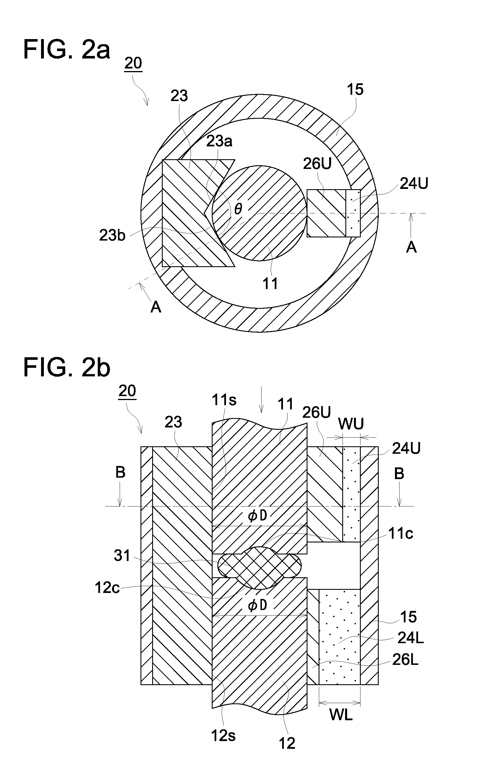
[0072]FIG. 2 is a diagram showing an example of a molding die according to the second preferred embodiment of the present invention, and shows the condition in the process of applying pressure to the glass material. FIG. 2a is a cross-sectional view diagram of a cross-section perpendicular to the direction of pressing the glass material (the press axis direction) and indicates the cross-section at B-B indicated in FIG. 2b. Further, FIG. 2b is a cross-sectional view diagram of a cross-section that is parallel to the press axis direction and indicates the cross-section at A-A indicated in FIG. 2a.

[0073]The molding die 20 shown in FIG. 2 is different from the molding die 10 described above in that the guiding member 23 is constituted of a V-block, the expansion member is made of a top expansion member 24U and a bottom expansion member 24L which respectively press against the top die 11 and the bottom die 12 via the spacers 26U and 26L. Since all other aspects of construction are simil...


PUM

PropertyMeasurementUnit
diametersaaaaaaaaaa
diametersaaaaaaaaaa
diametersaaaaaaaaaa

Abstract

A molding die with a simple structure, which produces an optical element of a low eccentricity degree, without narrowing the option for materials of the molding die and a method for producing an optical element by using the molding die are provided. The molding die includes a top die, bottom die, guiding member having a guiding surface kept in contact with the side faces of the top die and bottom die during the press molding of glass material, an expansion member for pressing the top die and bottom die against the guiding surface by thermal expansion by heating, and a supporting member for supporting the guiding member and expansion member. Among these members, the expansion member has the greatest thermal expansion coefficient. The press molding is applied to the glass material while the top die and bottom die are pressed against the guiding member by the thermal expansion of the expansion member.

Description

TECHNICAL FIELD[0001]The present invention relates to molding dies for manufacturing optical elements by press molding of glass materials, and to the manufacturing method of optical elements using the dies.BACKGROUND[0002]Recently, optical elements made of glass are widely being used, such as lenses for digital cameras, optical pick up lenses for DVDs, camera lenses for mobile phones, coupling lenses for optical communication.[0003]It has become more common to manufacture these optical elements made of glass using the press molding method in which a glass material is molded by applying pressure. As a press molding method for optical elements made of glass, conventionally, a method has been known in which in advance a glass material having a prescribed mass and shape is prepared and after heating the glass material along with a molding die, an optical element is obtained by press molding using the molding die.[0004]According to the size reduction and increase in accuracy of various t...

Claims


Application Information

Patent Timeline
Patent Type & Authority Applications(United States)
IPC IPC(8): C03B11/00
CPCC03B11/08C03B2215/73C03B2215/60C03B2215/03
Inventor SAKATA, TADAFUMI
Owner KONICA MINOLTA OPTO
Why Eureka
Try Eureka