
Radio resource management method, macro base station, and low-power node

a radio resource and macro technology, applied in the field of long-term evolution system, can solve the problems of user data throughput and call experience degradation, more problems, complex network deployment environment, etc., and achieve the effect of improving user experience and improving user data service performan

Active Publication Date: 2017-05-30
GUANGDONG OPPO MOBILE TELECOMM CORP LTD
View PDF8 Cites 0 Cited by
  • Summary
  • Abstract
  • Description
  • Claims
  • Application Information

AI Technical Summary

Benefits of technology

[0006]The embodiment of the present invention provides a method for radio resource management, a macro eNB and a low power node, to guarantee the data service continuity and reduce the call drop rate.
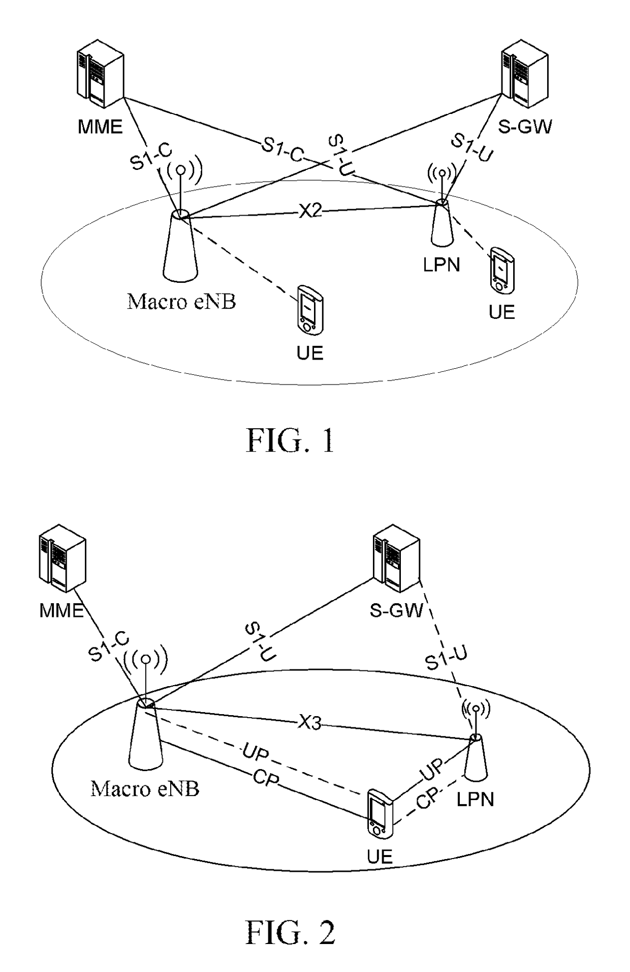
[0057]In summary, the distributed radio resource management system provided in the embodiment of the present invention can be used to make a macro eNB coordinate with a low power node, and jointly manage radio resources of a UE, thus making connections between network side devices and terminals no longer limited to the transmission performance of one link and be suitable for flexible scheduling and transmission way of data distribution between a variety of network side devices and the terminals. When the UE moves quickly and switches frequently between the SCs, the UE can timely obtain the stable control signaling, and the distributing way of user data can be flexibly adjusted between the base stations, and a mobility-related decision can be made quickly, which can ensure the data service continuity and enhance the performance of user data service and the user experience.

Problems solved by technology

However, with the increase of the SCs, the network deployment environment is becoming more complex, which brings more problems.
This is because the SC coverage range is much smaller as compared to the macro cell (MC), and the number of SCs is relatively large, therefore when the UE moves within the network, the signal quality of the radio link may change rapidly, resulting in frequent inter-cell handovers, and even leading to frequent data service interruptions or call drops or other problems, which also makes the user's data throughput and call experience degrade.
With the increasing number of SCs deployed by operators and individuals in the future, the abovementioned situation will become increasingly serious.

Method used


Image

  • Radio resource management method, macro base station, and low-power node
  • Radio resource management method, macro base station, and low-power node
  • Radio resource management method, macro base station, and low-power node

Examples


first embodiment

[0086]The First Embodiment

[0087]The macro eNB selects an appropriate LPN to provide a joint transmission service, and after determining the distributing strategy, it requests the LPN to agree on bearing the transmission of distributed data. A RRC connection (a CP connection) can be established between a LPN and a UE, after the UE accesses the LPN, the distribution bearer addition / modification / deletion may be notified by the LPN to the UE through the RRC signaling; in terms of data, the LPN obtains the downlink distributed data, transmitted to the UE, from the macro eNB. As shown in FIG. 5, it comprises the following steps:

[0088]in step 501, a UE accesses a macro cell, and performs the transmission of user data and control signaling with the macro eNB through the Uu radio interface.

[0089]In step 502, the macro eNB selects a LPN for the accessed UE to provide a joint transmission service and determines the distributing strategy according to situations such as the UE's service data nee...

second embodiment

[0108]The Second Embodiment

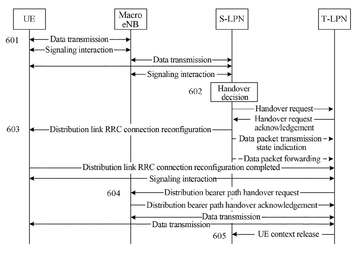
[0109]When providing the joint transmission service for the UE, the LPN executes the CMC on radio bearers between the LPN and the UE or on all radio bearers of the UE. The UE that accesses the macro cell establishes a CP connection and a UP connection with the LPN simultaneously, and the LPN configures the UE measurement and makes a handover decision (that is, the CMC function) by itself according to the measurement result. After indicating the UE that the handover completes, the source LPN (S-LPN) notifies the macro eNB of the change of the distributed data transmission path. As shown in FIG. 6, it comprises the following steps:

[0110]in step 601, the UE in the connected state and the macro eNB establish an UP connection for user data transmission and a CP connection for control signaling transmission at the radio interface, and, according to the distributing strategy determined by the macro eNB, the UE simultaneously establishes a UP connection and a CP c...

third embodiment

[0117]The Third Embodiment

[0118]When the macro eNB provides a joint transmission service for the UE, it performs the CMC on radio bearers between the macro eNB and the UE or all radio bearers of the user equipment. The UE which has accessed the macro cell also established the CP connection and the UP connection with the LPN simultaneously, and the macro eNB configures the UE to perform the measurement, and decides to hand over the UE to the new LPN to continue transmitting the distributed data according to the measurement result. As shown in FIG. 7, it comprises the following steps:

[0119]in step 701, the UE in the connected state establishes a UP connection for user data transmission and a CP connection for control signaling transmission with the macro eNB at the radio interface, and according to the distributing strategy determined by the macro eNB, the UE establishes a UP connection and a CP connection simultaneously with the LPN which bears the distributed data transmission.

[0120...


PUM


Abstract

Disclosed are a method for radio resource management, a macro eNB and a low power node. The method is applied to a long term evolution (LTE) system introduced with a low power node, including: a macro eNB selecting a low power node for an accessed user equipment to provide a joint transmission service; the low power node and the macro eNB jointly providing a radio resource management service for the user equipment. The macro eNB includes a selection unit and a first resource management unit. The low power node includes a second resource management unit and a data transmission unit.

Description

CROSS-REFERENCE TO RELATED APPLICATION(S)[0001]This application is the U.S. National Phase application of PCT application number PCT / CN2014 / 070883 having a PCT filing date of Jan. 20, 2014, which claims priority of Chinese patent application 201310130961.X filed on Apr. 16, 2013, the disclosures of which are hereby incorporated by reference.TECHNICAL FIELD[0002]The present document relates to the long-term evolution system, and more particularly, to a method for radio resource management, a macro eNB and a low power node.BACKGROUND OF THE RELATED ART[0003]With continuous evolution of wireless communication technologies and standards, the mobile packet service has been developed tremendously, and the data throughput capability of a single terminal is constantly increasing. Take the long-term evolution (LTE) system for example, at 20 Megabits per second (Mbps, also called M), a maximum of 100 Mbps downlink data transmission rate can be supported within the bandwidth, while in the LTE-...

Claims


Application Information

Patent Timeline
Patent Type & Authority Patents(United States)
IPC IPC(8): H04W72/04H04W28/16H04W16/32
CPCH04W72/04H04W28/16H04W16/32H04W76/15Y02D30/70
Inventor WANG, XIN
Owner GUANGDONG OPPO MOBILE TELECOMM CORP LTD
Learn More