Method and a system for false alarm reduction in motion detection by scanning cameras

a scanning camera and motion detection technology, applied in the direction of electromagnetic systems, television systems, instruments, etc., can solve the problems of system being very sensitive to false alarms, time duration needed by the system, and the rate of motion detection with scanning cameras suffers from a relatively high rate of false alarms, so as to facilitate motion detection of objects and reduce false alarms

Active Publication Date: 2017-06-06
PROTRACK
View PDF5 Cites 0 Cited by
  • Summary
  • Abstract
  • Description
  • Claims
  • Application Information

AI Technical Summary

Benefits of technology

[0012]It is hence one object of the invention to disclose a method for reducing false alarms in scanning camera facilitated motion detection of an object. The method comprising one or more steps selected in a non-limiting manner from a group consisting of setting a camera to observe a predefined area; continuously or non-continuously scanning by the camera of the said area for any motion; pausing the camera's scanning if a new motion is detected; analyzing the motion if it has not disappeared, while keeping the object within the camera's field of view; providing an alarm and possibly showing the motion if a motion that should be reported is obtained; and tracking the motion for a period of time at the discretion of the operator.
[0014]It is another object of the invention to disclose a method for reducing false alarms in scanning camera facilitated motion detection of an object. The method comprising one or more steps selected in a non-limiting manner from a group consisting of setting a camera to observe a pre-defined area; continuously or non-continuously scanning by said camera of the said area for any motion; pointing a secondary camera toward the detected motion and setting it to stop if new motion is detected; analyzing the motion by means of said secondary camera if the motion is still detected by said secondary camera, while keeping the object inside the secondary camera's field of view; providing an alarm and possibly showing the motion if a motion that should be reported is obtained; and tracking the motion for a period of time by said secondary camera at the discretion of the operator.

Problems solved by technology

Motion detection with scanning cameras suffers from a relatively high rate of false alarms.
Another limitation of motion detection with scanning cameras involves the time duration needed by the system to decide that a moving object was detected.
Unfortunately, the short detection time needed causes the system to be very sensitive to false alarms because there is not enough time to analyze the motion and to decide if the motion should be reported or is induced by nuisances such as moving trees that should be filtered out.
This is an unacceptable solution because it reduces the system area coverage rate.
This method does not give a solution to the long time duration needed to complete a cycle, nor to the false alarms caused by the virtual motions.

Method used


Image

  • Method and a system for false alarm reduction in motion detection by scanning cameras
  • Method and a system for false alarm reduction in motion detection by scanning cameras
  • Method and a system for false alarm reduction in motion detection by scanning cameras

Examples


example 1

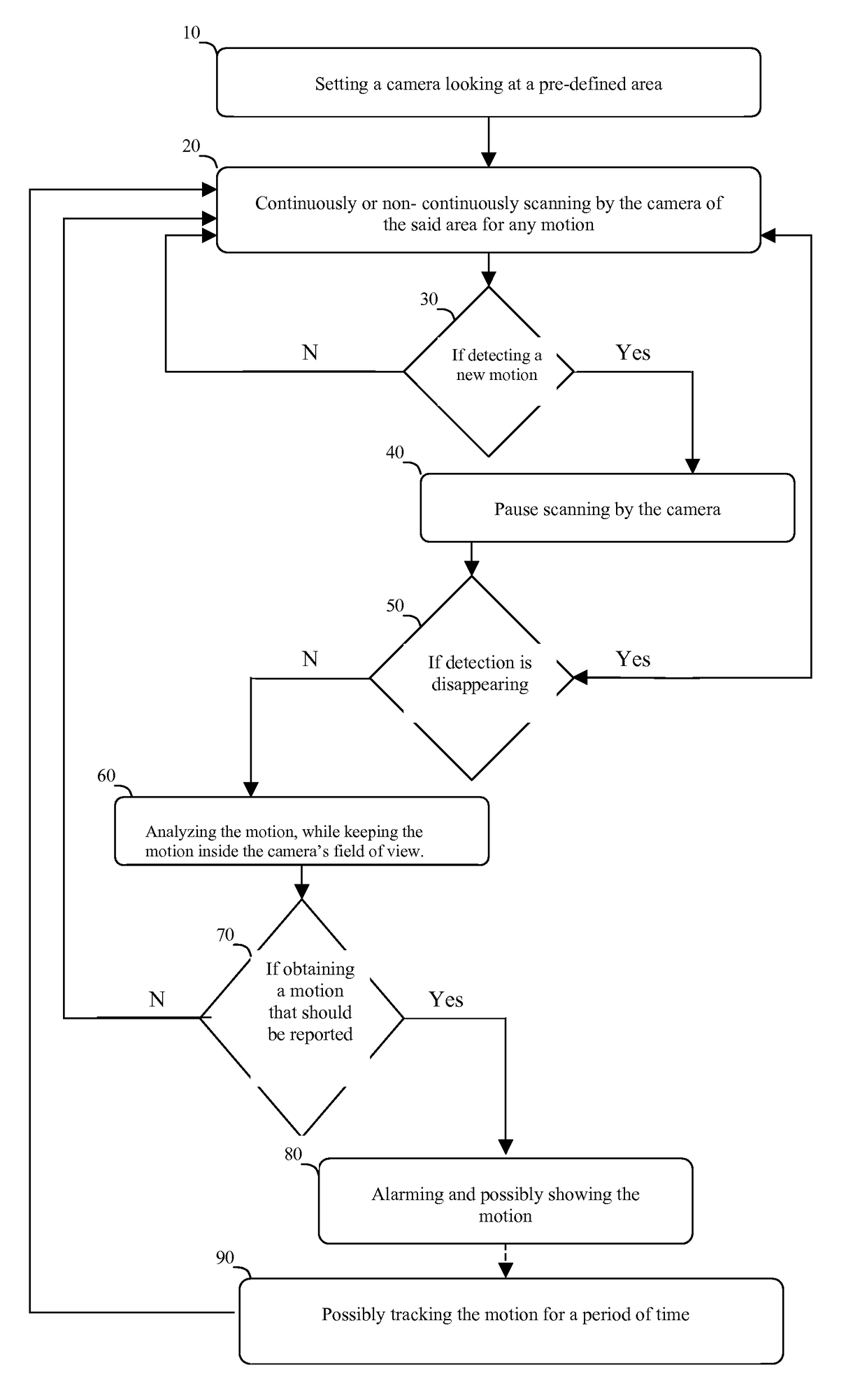
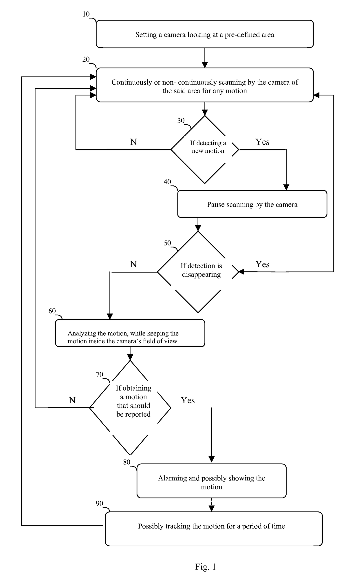
[0051]A scanning system with a single camera:

[0052]A camera with FOV (field of view) of 2 degrees is scanning a strip of 40 degrees (20 FOVs). The camera movements can be controlled by the system.

[0053]Assume that the system can detect motion while the camera is scanning and the detection resolution of the system is four pixels, i.e. the minimal translation that can be detected by the system is four pixels.

[0054]Let us assume the following system requirements: In order to provide an alert, the camera must observe a translation of more than 16 pixels at a speed of more than 2 pixels / second; any motion failing to meet this criterion will be considered unimportant background motions. The camera's scan rate should be as fast as possible and the alert must be provided in no more than one minute, assuming that no more than 2 moving objects exist in the scanning strip.

[0055]With these requirements, and if not using any of methods described herein, eight seconds are needed to detect the slo...

example 2

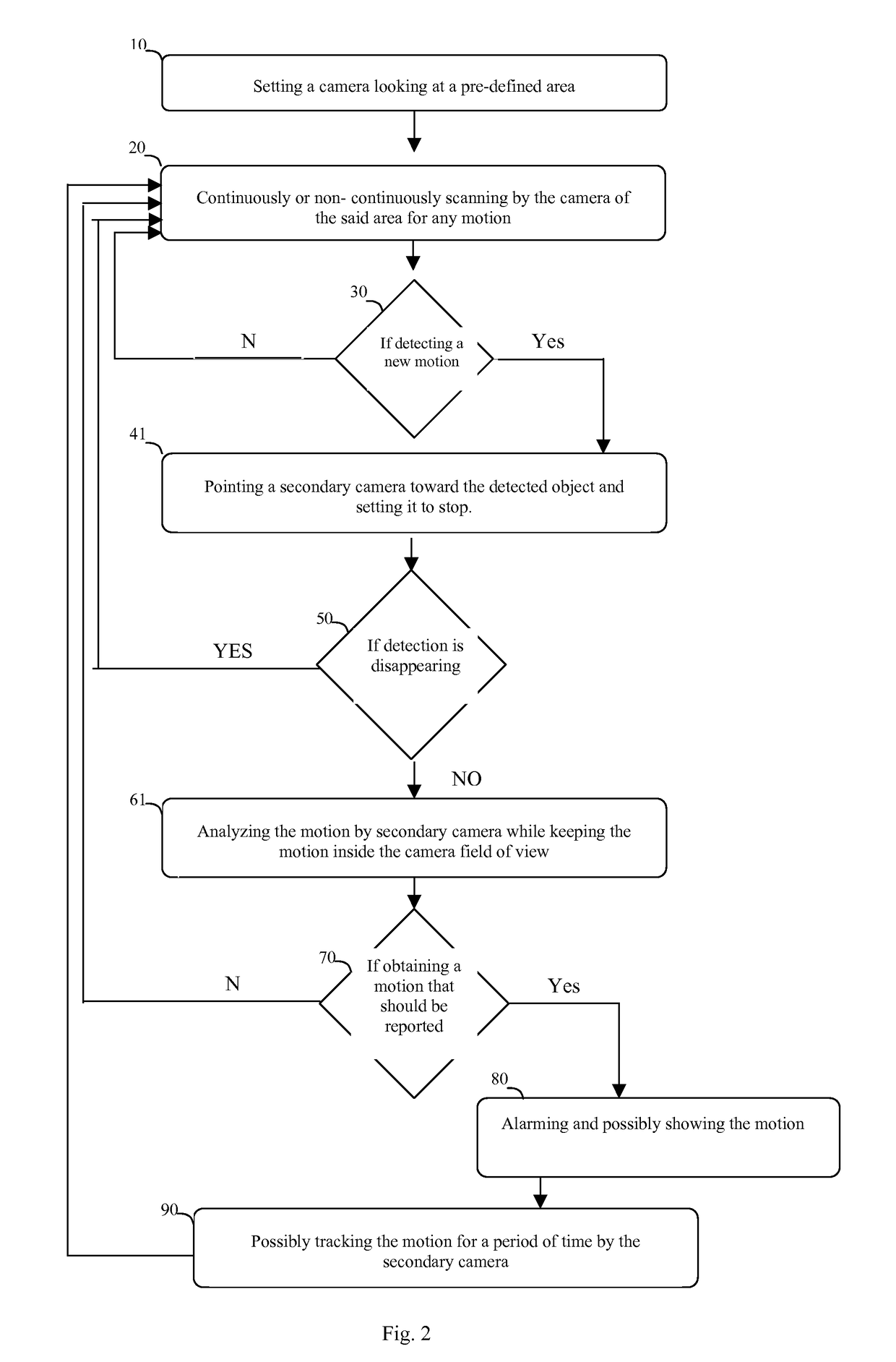
[0060]A scanning system with a scanning camera and a secondary camera:

[0061]A camera with FOV (field of view) of 2 degrees is scanning a strip of 40 degrees (20 FOVs). The camera movements can be controlled by the system.

[0062]Assume that the system can detect motion while the camera is scanning and the detection resolution of the system is four pixels, i.e. the minimal translation that can be detected by the system is four pixels.

[0063]The system is equipped with a secondary camera. When a new motion is detected by the scanning camera, the secondary camera can be directed to this detected motion in less than one second such that the detected motion will be approximately in the center of the field of view.

[0064]The secondary camera can track the motion if the object is going to exit the field of view.

[0065]Let assume the following system requirements: In order to provide an alert, the camera must observe a translation of more than 16 pixels having a speed above 2 pixels / second; othe...


PUM


Abstract

A method and a system for false alarm reduction in motion detection by scanning cameras. A method for reducing false alarms in scanning camera facilitated motion detection of an object, includes: setting a camera to observe a predefined area; continuously or non-continuously scanning by the camera of the said area for any motion; pausing the camera's scanning if a new motion is detected; analyzing the motion if it has not disappeared, while keeping the object within the camera's field of view; providing an alarm and possibly showing the motion if a motion that should be reported is obtained; and tracking the motion for a period of time at the discretion of the operator.

Description

CROSS-REFERENCE TO RELATED APPLICATION[0001]The present application claims the benefit of priority of Israeli Patent Application No. 190776, filed Apr. 10, 2008, the content of which are incorporated by reference in its entirety.BACKGROUND[0002]1. Field of the Invention[0003]The present invention generally pertains to methods and systems for false alarm reduction in motion detection by scanning cameras.[0004]2. Discussion of Related Art[0005]Motion detection with scanning cameras suffers from a relatively high rate of false alarms. These false alarms can be caused by many factors such as stains on the camera glass, sun reflections, dead pixels in a thermal camera, etc., which induce virtual motion relative to the image that is not related to any real moving object in the area.[0006]Another limitation of motion detection with scanning cameras involves the time duration needed by the system to decide that a moving object was detected. Due to the short time that an object is exposed to...

Claims


Application Information

Patent Timeline
Patent Type & Authority Patents(United States)
IPC IPC(8): H04N7/18G08B13/196G01S3/786H04N5/232H04N5/14
CPCG08B13/19643G01S3/7864G08B13/1961G08B13/19602H04N5/232H04N5/144H04N23/61
Inventor ROSENBERG, YOAV
Owner PROTRACK
Why Eureka
Try Eureka